ii
How to Use This Manual
■ Finding a Function
The following methods can be used to search for details of a function in this manual:
• Searching from CONTENTS
CONTENTS lists the contents in this manual in the order of description.
• Searching from registers
The address at which a register is located is not mentioned in this manual. To check the
address of a register, refer to "■ I/O MAP" in the device data sheet.
■ Chapters
This manual explains one peripheral function in one chapter.
■ Terminology
This manual uses the following terminology.
■ Notations
The notations in "■ Register Configuration" in this manual are explained below:
• bit: bit number
• Field: bit field name
• Attribute: Attributes for read access and write access of each bit
- R: Read-only
- W: Write-only
- R/W: Readable/Writable
- —: Undefined
• Initial value: Initial value of a bit after a reset
- 0: The initial value is "0".
- 1: The initial value is "1".
- X: The initial value is undefined.
Multiple bits are indicated in this manual in the following way.
- Example 1: bit7:0 represents bit7 to bit0.
- Example 2: SCM[2:0] represents SCM2 to SCM0.
The values such as those indicating addresses are written in this manual in the following ways:
- Hexadecimal number: The prefix "0x" is attached to the beginning of a value
(e.g.: 0xFFFF).
- Binary number: The prefix "0b" is attached to the beginning of a value (e.g.: 0b1111).
- Decimal number: Only the number is used (e.g.: 1234).
In this manual, "n" in a pin name and a register abbreviation represents the channel number.
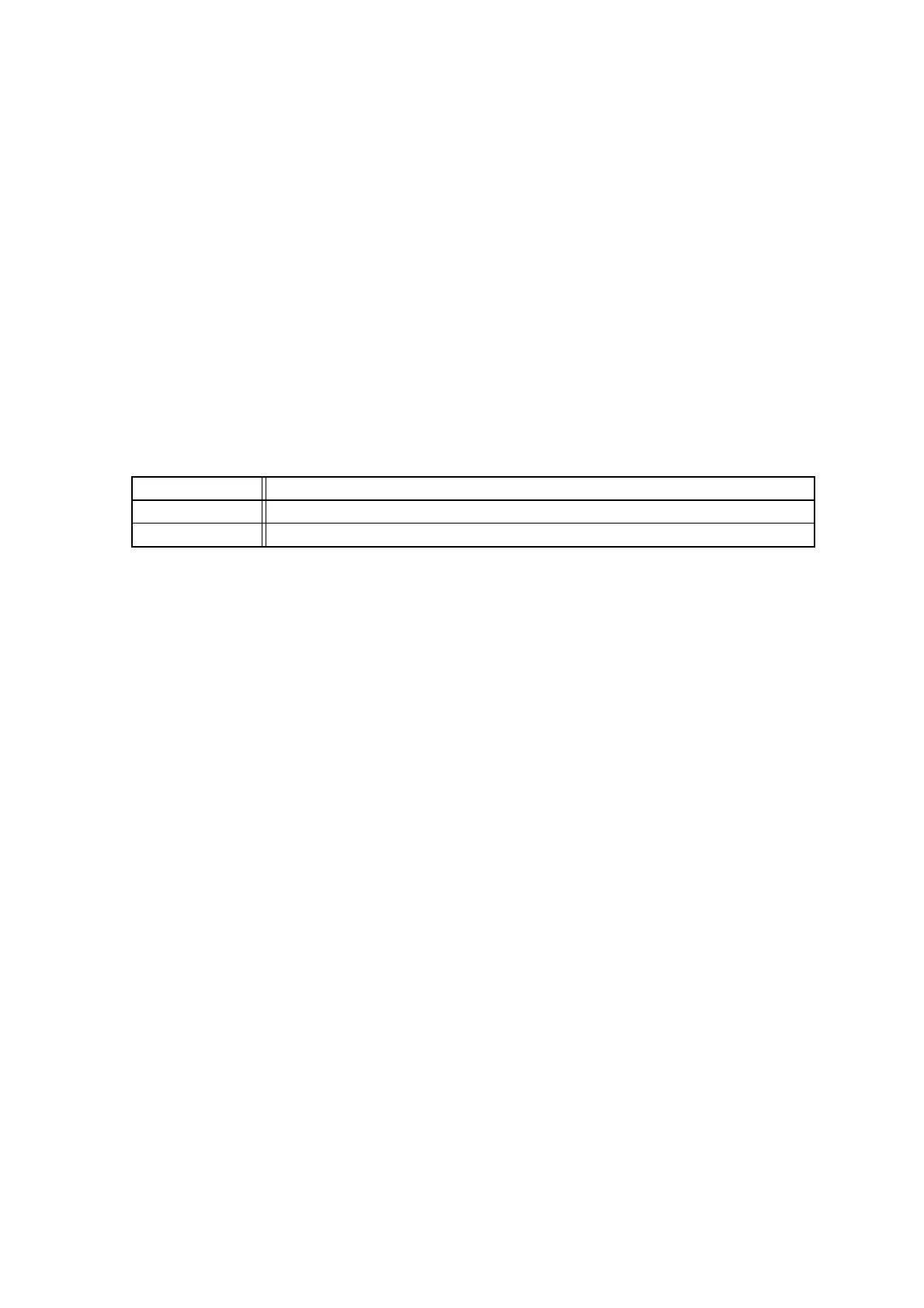
Ter m Explanation
Word Indicates an access in unit of 16 bits.
Byte Indicates an access in unit of 8 bits.