Home
Fujitsu
Server
PRIMERGY MX130 S2 Upgrade and maintenance manua
Page 128
Fujitsu PRIMERGY MX130 S2 Upgrade and maintenance manua - Page 128
256 pages
Manual
To Next Page
To Next Page
To Previous Page
To Previous Page
Loading...
128
Upgrade and Mai
ntenance Manual
MX130
S2
HDDs and accessible drives
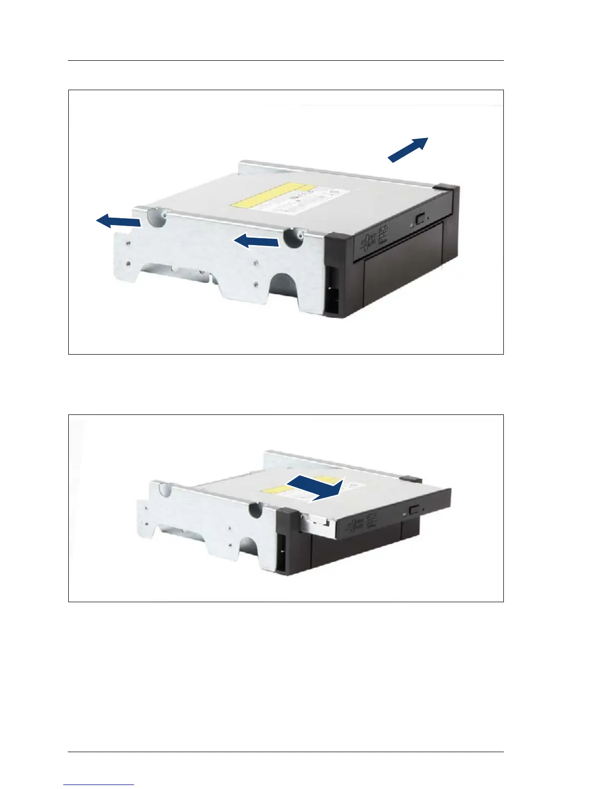
Figure 65: Removing the screws
Ê
Remove the three screws.
Figure 66:
Removing the ODD out
of
the 5.25-inch ODD/HDD brac
ket
Ê
Remove the ODD from its inst
allation b
ay
.
127
129
Table of Contents
Main Page
Default Chapter
2
Copyright and Trademarks
2
Table of Contents
5
Version History
15
1 Introduction
17
Where to Find Which Information
18
Notational Conventions
19
2 Before You Start
21
Classification of Procedures
23
Customer Replaceable Units (CRU)
23
Upgrade and Repair Units (URU)
24
Field Replaceable Units (FRU)
25
Average Task Duration
26
Tools You Need at Hand
27
Documents You Need at Hand
28
3 Important Information
31
Safety Instructions
31
Energy Star
39
CE Conformity
42
FCC Class a Compliance Statement
43
Environmental Protection
44
4 Basic Hardware Procedures
47
Using Diagnostics Information
47
Opening the Server
48
Shutting down the Server
48
Removing the Server Cover
51
Opening the Front Cage
52
MX130 S2 Upgrade and Maintenance Manual
53
Closing the Front Cage
53
Closing the Server
54
Mounting the Server Cover
54
Connecting the Server to the Mains
55
Switching on the Server
58
5 Basic Software Procedures
59
Starting the Maintenance Task
59
Disabling Bitlocker Functionality
59
Removing Backup and Optical Disk Media
60
Verifying and Configuring the Backup Software Solution
61
Completing the Maintenance Task
62
Updating the System Board BIOS
62
Updating RAID Controller Firmware
63
Enabling Option ROM Scan
64
Verifying and Configuring the Backup Software Solution
64
Viewing the System Event Log (SEL)
65
Enabling Bitlocker Functionality
66
Performing a RAID Array Rebuild
67
Looking up Changed MAC Addresses
67
Using the Chassis ID Prom Tool
68
6 Power Supply
69
Standard PSU
70
Replacing the Standard PSU
70
Required Tools
70
Preliminary Steps
70
Disconnecting Internal Power Cables
71
Removing the PSU
72
Installing the PSU
73
Reconnecting Internal Power Cables
76
Concluding Steps
77
7 Hdds and Accessible Drives
79
Basic Procedure
81
Mounting Order
82
Installing 3.5-Inch HDD in HDD1 / HDD2 Chassis Bay
83
Required Tools
83
Preliminary Steps
83
Installing a 3.5-Inch HDD in HDD 1/HDD 2 Chassis Bay
84
Installing 3.5-Inch HDD in HDD1 / HDD2 Chassis Bay
84
Concluding Steps
87
Removing 3.5-Inch HDD out of HDD1 / HDD2 Chassis Bay
88
. 88 Required Tools
88
Preliminary Steps
88
Removing a 3.5-Inch HDD out of HDD 1/HDD 2 Chassis Bay
89
Concluding Steps
91
Installing Additional 3.5-Inch HDD in 3.5-Inch Chassis Bay
91
Required Tools
91
Preliminary Steps
91
Installing an Additional 3.5-Inch HDD in 3.5-Inch Chassis Bay
92
Concluding Steps
93
Removing Additional 3.5-Inch HDD out of 3.5-Inch Chassis Bay
94
Required Tools
94
Preliminary Steps
94
Removing an Additional 3.5-Inch HDD out of 3.5-Inch Chassis Bay
95
Concluding Steps
96
Installing Additional 3.5-Inch HDD in 5.25-Inch Dummy Cover
97
Required Tools
97
Preliminary Steps
97
Installing a 3.5-Inch HDD in 5.25-Inch Dummy Cover
98
Concluding Steps
100
Removing 3.5-Inch HDD out of
100
Inch Dummy Cover
100
Required Tools
100
Preliminary Steps
100
Removing 3.5-Inch HDD out of 5.25-Inch Dummy Cover
100
Removing a 3.5-Inch HDD out of 5.25-Inch Dummy Cover
101
Concluding Steps
103
Installing Additional 3.5-Inch HDD in 5.25-Inch ODD/HDD Bracket
103
Required Tools
103
Preliminary Steps
103
Installing an Additional 3.5-Inch HDD in ODD/HDD Bracket
104
Concluding Steps
106
Removing 3.5-Inch HDD out of 5.25-Inch ODD/HDD Bracket
106
Required Tools
106
Preliminary Steps
107
Removing an Additional 3.5-Inch HDD out of the 5.25-Inch ODD/HDD Bracket
107
Concluding Steps
110
Installing 5.25-Inch Dummy Cover
110
Required Tools
110
Preliminary Steps
110
Installing a 5.25-Inch Dummy Cover
111
Concluding Steps
112
Removing 5.25-Inch Dummy Cover
112
Required Tools
112
Preliminary Steps
112
Removing a 5.25-Inch Dummy Cover
113
MX130 S2 Upgrade and Maintenance Manual
113
Concluding Steps
114
Installing ODD in 5.25-Inch Chassis Bay
115
Required Tools
115
Preliminary Steps
115
Installing an ODD in 5.25-Inch Chassis Bay
116
Concluding Steps
117
Removing ODD out of 5.25-Inch Chassis Bay
118
Required Tools
118
Preliminary Steps
118
Removing an ODD out of 5.25-Inch Chassis Bay
119
Concluding Steps
120
Installing Slimline ODD in 5.25-Inch ODD/HDD Bracket
121
Required Tools
121
Preliminary Steps
121
Installing a Slimline ODD in 5.25-Inch ODD/HDD Bracket
122
Concluding Steps
124
Removing Slimline ODD out of 5.25-Inch ODD/HDD Bracket
125
Required Tools
125
Preliminary Steps
125
Removing a Slimline ODD out of 5.25-Inch ODD/HDD Bracket
126
Concluding Steps
129
Installing Backup Drive in 5.25-Inch Chassis Bay
130
Required Tools
130
Preliminary Steps
130
Installing a Backup Drive in 5.25-Inch Chassis Bay
131
Concluding Steps
132
Removing Backup Drive out of 5.25-Inch Chassis Bay
133
Required Tools
133
Preliminary Steps
133
Removing Backup Drive out of 5.25-Inch Chassis Bay
134
Concluding Steps
135
Installing Slimline ODD in Slimline Chassis Bay
136
Required Tools
136
Preliminary Steps
136
Removing the ODD Filler Cover
137
Installing the ODD
138
Concluding Steps
141
Replacing Slimline ODD out of Slimline Chassis Bay
142
Required Tools
142
Preliminary Steps
142
Replacing a Slimline ODD out of Slimline Chassis Bay
143
Concluding Steps
144
8 System Fan
145
Replacing the System Fan Module
146
Required Tools
146
Preliminary Steps
146
Removing the System Fan Module
147
Installing the System Fan Module
150
Concluding Steps
157
9 Expansion Cards
159
Basic Procedure
160
Expansion Cards
161
Installing Expansion Cards
161
Required Tools
161
Preliminary Steps
161
Removing a PCI Slot Bracket
162
Installing an Expansion Card
163
Connecting Cables to the Expansion Card
165
Concluding Steps
165
Removing Expansion Cards
165
Required Tools
165
Preliminary Steps
166
Removing an Expansion Card
166
Installing a PCI Slot Bracket
167
Concluding Steps
167
Installing Esata Cable
168
Required Tools
168
Preliminary Steps
168
Installing an Esata Cable (Optional for Specific Markets)
168
Connecting Cable of the Esata Cable to Connector
170
Concluding Steps
170
Removing Esata Cable
170
Required Tools
171
Preliminary Steps
171
MX130 S2 Upgrade and Maintenance Manual
171
Disconnecting Esata Cable (Optional for Specific Markets)
171
Removing an Esata Cable
172
Concluding Steps
172
Additional Tasks
173
Mounting Expansion Card Slot Brackets
173
Required Tools
173
Network Adapter D2907
174
Network Adapter D2745
176
10 Main Memory
179
Basic Procedure
180
Memory Sequence
180
Operation Modes
181
Installing Memory Modules
182
Required Tools
182
Preliminary Steps
182
Installing a Memory Module
182
Concluding Steps
183
Removing Memory Modules
184
Required Tools
184
Preliminary Steps
184
Removing a Memory Module
184
Concluding Steps
185
11 Processors
187
Basic Procedure
188
Replacing the Processor Heat Sink
188
Required Tools
188
Preliminary Steps
188
Removing the Processor Heat Sink
189
Thermal Paste
190
Installing the Processor Heat Sink
190
Concluding Steps
191
Replacing the Processor
191
Required Tools
191
Preliminary Steps
192
Removing the Processor Heat Sink
192
Removing the Processor
192
Installing the Processor
194
Applying Thermal Paste
196
Installing the Processor Heat Sink
197
Concluding Steps
197
12 System Board and Components
199
Replacing the CMOS Battery
200
Required Tools
200
Preliminary Steps
201
Removing the CMOS Battery
201
Installing the CMOS Battery
202
Concluding Steps
203
Trusted Platform Module (TPM)
204
Installing the TPM Board
204
Required Tools
204
Preliminary Steps
204
Installing the TPM Board
205
Concluding Steps
208
Removing the TPM Board
209
Required Tools
209
Preliminary Steps
210
Removing the TPM Board
211
Concluding Steps
212
Replacing the System Board
213
Required Tools
213
Preliminary Steps
214
Removing the System Board
215
Installing the System Board
218
Mounting the System Board
218
Concluding Steps
221
13 Front Panel and Front USB
223
Replacing the Front Panel Indicators
224
Required Tools
224
Preliminary Steps
224
Removing the On/Off Button
225
Removing the HDD Activity LED
226
Removing the Cable for On/Off Button and HDD Activity LED
227
Installing the On/Off Button and the HDD Activity LED
228
Concluding Steps
228
Replacing the Front USB Board
229
Required Tools
229
Preliminary Steps
229
Removing the Defective Front USB Board
230
Installing the New Front USB Board
231
Concluding Steps
232
14 Cables
233
Cabling Overview
234
Overview of Used Cables
234
Cabling
235
Power Cabling
235
Data Cabling
237
Replacing the Power Cable
239
Required Tools
239
Preliminary Steps
239
Removing the Power Cable
240
Installing the Power Cable
242
Concluding Steps
243
15 Appendix
245
Mechanical Overview
245
Server Front
245
Server Rear
246
Server Interior
247
Configuration Tables
248
Mounting Order for Hdds
248
Memory Board Configuration
248
Expansion Card Configuration Table
248
Connectors and Indicators
249
Connectors and Indicators on the System Board
249
Onboard Connectors
249
Onboard Settings
250
I/O Panel Connectors
251
I/O Panel Indicators
252
Connectors and Indicators on the Front Panel
253
Minimum Startup Configuration
254
MX130 S2 Upgrade and Maintenance Manual
255
Related product manuals
Fujitsu PRIMERGY RX200 S2
307 pages
Fujitsu PRIMERGY TX150 S2
163 pages
Fujitsu Primergy RX300 S2
311 pages
Fujitsu PRIMERGY TX200 S2
317 pages
Fujitsu Primergy RX100 S2
275 pages
Fujitsu PRIMERGY TX140 S2
86 pages
Fujitsu PRIMERGY BX920 S2
102 pages
Fujitsu PRIMERGY TX100 S2
66 pages
Fujitsu PRIMERGY RX900 S2
114 pages
Fujitsu Primergy BX900 S2
108 pages
Fujitsu PRIMERGY RX2540 M1
438 pages
Fujitsu PRIMERGY RX4770 M2
84 pages