Home
Fujitsu
Server
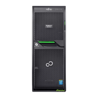
PRIMERGY TX140 S2
Upgrade And Maintenance Manual
Page 66 (Locking the Server)
Fujitsu PRIMERGY TX140 S2 - Locking the Server
332 pages
Manual
To Next Page
To Next Page
To Previous Page
To Previous Page
Loading...
66
Upgrade and Mai
ntenance Manual
TX140
S2
Basic hardware procedures
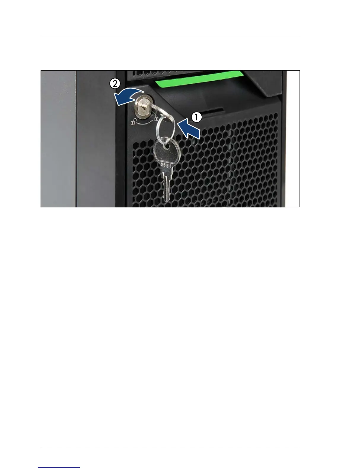
4.5.2.4
Locking the server
Figure 22: Loc
king the server
Ê
If required by security regulations, insert the key into the lock on the front
panel and lock the s
erver
.
65
67
Table of Contents
Main Page
Default Chapter
2
Copyright and Trademarks
2
Version History
6
Table of Contents
7
1 Introduction
19
Notational Conventions
20
2 Before You Start
21
Classification of Procedures
22
Customer Replaceable Units (CRU)
23
Upgrade and Repair Units (URU)
23
Field Replaceable Units (FRU)
24
Average Task Duration
25
Tools You Need at Hand
26
Documents You Need at Hand
28
3 Important Information
31
Safety Instructions
31
Energy Star
39
CE Conformity
39
FCC Class a Compliance Statement
40
Environmental Protection
41
4 Basic Hardware Procedures
43
Using Diagnostics Information
43
Locating the Defective Server
43
Determining the Error Class
44
Global Error Indicator
44
Customer Self Service (CSS) Indicator
44
Locating the Defective Component
45
Local Diagnostic Indicators on the Front
45
Local Diagnostic Indicators on the System Board
45
Shutting down the Server
46
Disconnecting the Server from the Mains
46
Getting Access to the Component
47
Rack Model
47
Extending the Server out of the Rack
47
Removing the Server from the Rack
49
Removing the Top Cover
51
Removing the Rack Front Cover
52
Tower Model
53
Removing the Side Cover
53
Removing the HDD Bay Cover
55
Removing the Front Cover
56
Reassembling
58
Rack Model
58
Installing the Rack Front Cover
58
Installing the Top Cover
59
Mounting the Server in the Rack
60
Sliding the Server into the Rack
62
Tower Model
63
Installing the Front Cover
63
Installing the HDD Bay Cover
64
Installing the Side Cover
65
Locking the Server
66
Connecting the Server to the Mains
67
Switching on the Server
68
5 Basic Software Procedures
69
Starting the Maintenance Task
69
Disabling Bitlocker Functionality
69
Disabling SVOM Boot Watchdog Functionality
70
Viewing Boot Watchdog Settings
70
Configuring Boot Watchdog Settings
71
Removing Backup and Optical Disk Media
72
Verifying and Configuring the Backup Software Solution
73
Note on Server Maintenance in a Multipath I/O Environment
73
Switching on the ID Indicator
75
Completing the Maintenance Task
75
Updating or Recovering the System Board BIOS and Irmc
75
Updating or Recovering the System Board BIOS
76
Updating or Recovering the Irmc
77
Verifying System Information Backup / Restore
79
Updating RAID Controller Firmware
80
Enabling Option ROM Scan
81
Verifying and Configuring the Backup Software Solution
82
Resetting the Boot Retry Counter
83
Viewing the Boot Retry Counter
83
Enabling SVOM Boot Watchdog Functionality
85
Enabling Replaced Components in the System BIOS
85
Verifying the Memory Mode
86
Verifying the System Time Settings
87
Viewing and Clearing the System Event Log (SEL)
87
Viewing the SEL
87
Clearing the SEL
88
Updating the NIC Configuration File in a Linux Environment
89
Enabling Bitlocker Functionality
90
Performing a RAID Array Rebuild
91
Looking up Changed MAC / WWN Addresses
92
Looking up MAC Addresses
92
Looking up WWN Addresses
92
Using the Chassis ID Prom Tool
93
Configuring LAN Teaming
94
After Replacing / Upgrading LAN Controllers
94
After Replacing the System Board
94
Switching off the ID Indicator
95
Specifying the Chassis Model
95
Performing a Fan Test after Replacing a Defective Fan
96
6 Power Supply
99
Basic Information
99
Standard Power Supply
100
Replacing the Standard Power Supply Unit
100
Preliminary Steps
100
Removing the Defective Standard Power Supply Unit
101
Installing the New Standard Power Supply Unit
104
Concluding Steps
106
Redundant Power Supply
106
Installing a Hot-Plug Power Supply Unit
106
Preliminary Steps
106
Removing the Dummy Cover
107
Installing a Hot-Plug Power Supply Unit
108
Concluding Steps
108
Removing a Hot-Plug Power Supply Unit
109
Preliminary Steps
109
Removing a Hot-Plug Power Supply Unit
110
Installing the Dummy Cover
111
Replacing a Hot-Plug Power Supply Unit
111
Preliminary Steps
112
Removing the Defective Hot-Plug Power Supply Unit
112
Installing the New Hot-Plug Power Supply Unit
112
Concluding Steps
113
Replacing the Power Distribution Board
113
Preliminary Steps
113
Removing the Hot-Plug Power Supply Units
113
Replacing the Defective Power Distribution Board
114
Installing the Hot-Plug Power Supply Units
115
Concluding Steps
116
Converting a Standard Power Supply to a Redundant Power Supply
116
Preliminary Steps
116
Removing the Standard Power Supply Unit
117
Installing the Upgrade Kit
117
Concluding Steps
119
7 Hard Disk Drives / Solid State Drives
121
Basic Information
122
Inch HDD / SSD Configurations
123
Mounting Order
123
HDD / SSD Naming Scheme
123
Installing 2.5-Inch HDD / SSD Modules
124
Preliminary Steps
124
Removing a 2.5-Inch HDD / SSD Dummy Module
124
Installing a 2.5-Inch HDD / SSD Module
125
Concluding Steps
126
Removing 2.5-Inch HDD / SSD Modules
126
Preliminary Steps
126
Removing a 2.5-Inch HDD / SSD Module
127
Installing a 2.5-Inch HDD / SSD Dummy Module
128
Concluding Steps
128
Replacing a 2.5-Inch HDD / SSD Module
129
Preliminary Steps
129
Removing a 2.5-Inch HDD / SSD Module
130
Installing a 2.5-Inch HDD / SSD Module
130
Concluding Steps
130
Replacing a 2.5-Inch HDD SAS / SATA Backplane
130
Preliminary Steps
130
Removing the Defective 2.5-Inch HDD SAS / SATA Backplane
131
Installing the New 2.5-Inch HDD SAS / SATA Backplane
132
Concluding Steps
132
Inch HDD Configurations
133
Mounting Order
133
HDD Naming Scheme
133
Installing 3.5-Inch HDD Modules
134
Preliminary Steps
134
Removing a 3.5-Inch HDD Dummy Module
134
Installing a 3.5-Inch HDD Module
135
Concluding Steps
136
Removing 3.5-Inch HDD Modules
137
Preliminary Steps
137
Removing a 3.5-Inch HDD Module
138
Installing a 3.5-Inch HDD Dummy Module
139
Concluding Steps
139
Replacing a 3.5-Inch HDD Module
140
Preliminary Steps
140
Removing a 3.5-Inch HDD Module
141
Installing a 3.5-Inch HDD Module
141
Concluding Steps
141
Replacing the 3.5-Inch HDD SAS Backplane
141
Preliminary Steps
141
Removing the Defective 3.5-Inch HDD SAS Backplane
142
Installing the New 3.5-Inch HDD SAS Backplane
145
Concluding Steps
147
8 System Fan and Air Duct
149
Basic Information
150
Handling the Fan Module
151
Preliminary Steps
151
Removing the Fan Module
151
Installing the Fan Module
152
Concluding Steps
153
Replacing the System Fan
153
Preliminary Steps
153
Removing the Defective System Fan
154
Installing the New System Fan
157
Concluding Steps
157
9 Expansion Cards and Backup Units
159
Basic Information
160
Handling Slot Brackets
162
Installing a Slot Bracket
162
Removing a Slot Bracket
169
Handling SFP+ Transceiver Modules
170
Installing SFP+ Transceiver Modules
170
Removing an SFP+ Transceiver Module
173
Expansion Cards and Riser Card
176
Installing Expansion Cards
176
Preliminary Steps
176
Removing the PCI Slot Bracket
177
Installing an Expansion Card
178
Concluding Steps
179
Removing Expansion Cards
180
Preliminary Steps
180
Removing an Expansion Card
181
Installing a PCI Slot Bracket
182
Concluding Steps
182
Replacing Expansion Cards
183
Preliminary Steps
183
Removing the Defective Expansion Card
184
Installing the New Expansion Card
184
Concluding Steps
184
Replacing the Riser Card
185
Preliminary Steps
185
Removing the Defective Riser Card
185
Installing the New Riser Card
186
Concluding Steps
187
Replacing the TFM
188
Preliminary Steps
188
Removing the Defective TFM
188
Installing the New TFM
189
Concluding Steps
189
Backup Units
190
Basic Information
190
Installing an FBU
190
Preliminary Steps
190
Installing TFM to the RAID Controller (if Applicable)
191
Installing the FBU in the Holder
192
Installing the FBU Holder into the Chassis
193
Connecting the FBU Adapter Cable to the TFM
195
Concluding Steps
195
Installing a BBU
196
Preliminary Steps
196
Connecting the BBU Cable to the BBU
196
Installing the BBU in the Holder
197
Installing the BBU Holder into the Chassis
197
Connecting the BBU Cable to a Controller
197
Concluding Steps
198
Removing an FBU
199
Preliminary Steps
199
Disconnecting the FBU Adapter Cable from the TFM
199
Removing the FBU Holder from the Chassis
200
Concluding Steps
200
Removing a BBU
201
Preliminary Steps
201
Disconnecting the BBU Cable from the Controller
201
Removing the BBU Holder from the Chassis
201
Concluding Steps
201
Replacing an FBU
202
Preliminary Steps
202
Removing the Defective FBU
202
Installing the New FBU
204
Concluding Steps
204
Replacing a BBU
204
Preliminary Steps
204
Removing the Defective BBU
205
Installing the New BBU
206
Concluding Steps
206
10 Main Memory
209
Basic Information
209
Memory Sequence
210
Operation Modes
211
Removing Memory Modules
211
Preliminary Steps
211
Removing a Memory Module
212
Concluding Steps
212
Installing Memory Modules
213
Preliminary Steps
213
Installing a Memory Module
213
Concluding Steps
214
Replacing Memory Modules
214
Preliminary Steps
214
Removing the Defective Memory Module
215
Installing the New Memory Module
215
Concluding Steps
215
11 Processors
217
Basic Information
218
Upgrading or Replacing the Processor
218
Preliminary Steps
218
Removing the Processor Heat Sink
219
Removing the Processor
220
Installing the Processor
221
Applying Thermal Paste
223
Installing the Processor Heat Sink
225
Concluding Steps
227
Replacing the Processor Heat Sink
227
Preliminary Steps
227
Concluding Steps
228
12 Accessible Drives
229
Basic Information
230
Installing Accessible Drives
231
Preliminary Steps
231
Removing Accessible Drive Dummy Covers
232
(If Applicable)
234
Installing the Slimline Optical Disk Drive in the Slide-In Unit (if Applicable)
236
Installing an Accessible Drive
237
Concluding Steps
239
Removing Accessible Drives
239
Preliminary Steps
239
Removing an Accessible Drive
240
Installing Accessible Drive Dummy Covers
241
Concluding Steps
242
Replacing Accessible Drives
243
Preliminary Steps
243
Removing the Defective Accessible Drive
243
Installing the New Accessible Drive
244
Concluding Steps
244
13 Front Panel Module
245
Replacing the Front Panel Module
246
Preliminary Steps
246
Removing the Defective Front Panel Module
247
Installing the New Front Panel Module
249
Concluding Steps
250
14 System Board and Components
251
Basic Information
251
Replacing the CMOS Battery
252
Preliminary Steps
252
Replacing the Defective CMOS Battery
253
Concluding Steps
254
USB Flash Module (UFM)
255
Installing the UFM
255
Preliminary Steps
255
Concluding Steps
256
Software Configuration
257
Removing the UFM
257
Preliminary Steps
257
Removing the UFM
258
Concluding Steps
258
Replacing the UFM
259
Preliminary Steps
259
Removing the Defective UFM
259
Installing the New UFM
260
Concluding Steps
261
Software Configuration
262
Trusted Platform Module (TPM)
262
Installing the TPM
262
Preliminary Steps
262
Installing the TPM
263
Concluding Steps
265
Removing the TPM
266
Preliminary Steps
266
Removing the TPM
267
Concluding Steps
269
Replacing the TPM
270
Preliminary Steps
270
Removing the Defective TPM
271
Installing the New TPM
271
Concluding Steps
271
Replacing the System Board
272
Preliminary Steps
274
Removing the Defective System Board
274
Installing the New System Board
277
Swapping the Processor
279
Concluding Steps
283
15 Converting a Tower Model to a Rack Model
285
Preliminary Steps
285
Converting a Tower Model to a Rack Model
286
Concluding Steps
298
16 Cabling
299
List of Used Cables
300
Cabling Plans
301
Replacing the Intrusion Switch Cable
308
Preliminary Steps
308
Removing the Defective Intrusion Switch Cable
308
Installing the New Intrusion Switch Cable
311
Concluding Steps
313
17 Appendix
315
Mechanical Overview
315
Server Front
315
Server Rear
317
Server Interior
318
Connectors and Indicators
320
Connectors and Indicators on the System Board
320
Onboard Connectors
320
Onboard Indicators and Controls
322
I/O Panel Connectors
324
I/O Panel Indicators
325
PSU Indicator (Only Hot-Plug Psus)
326
Connectors and Indicators on the Front Panel
326
Front Panel Connectors
326
Front Panel Controls and Indicators
327
Onboard Settings
329
Minimum Startup Configuration
330
Other manuals for Fujitsu PRIMERGY TX140 S2
Operating Manual
86 pages
Related product manuals
Fujitsu PRIMERGY TX140 S1
86 pages
Fujitsu PRIMERGY TX140 S1p
9 pages
Fujitsu PRIMERGY TX150 S2
163 pages
Fujitsu PRIMERGY TX100 S2
66 pages
Fujitsu PRIMERGY TX200 S2
317 pages
Fujitsu PRIMERGY RX200 S2
307 pages
Fujitsu Primergy RX300 S2
311 pages
Fujitsu Primergy RX100 S2
275 pages
Fujitsu PRIMERGY BX920 S2
102 pages
Fujitsu PRIMERGY RX900 S2
114 pages
Fujitsu Primergy BX900 S2
108 pages
PRIMERGY MX130 S2 Upgrade and maintenance manua
256 pages