11 Schematics and Diagrams
M1207026 11-3
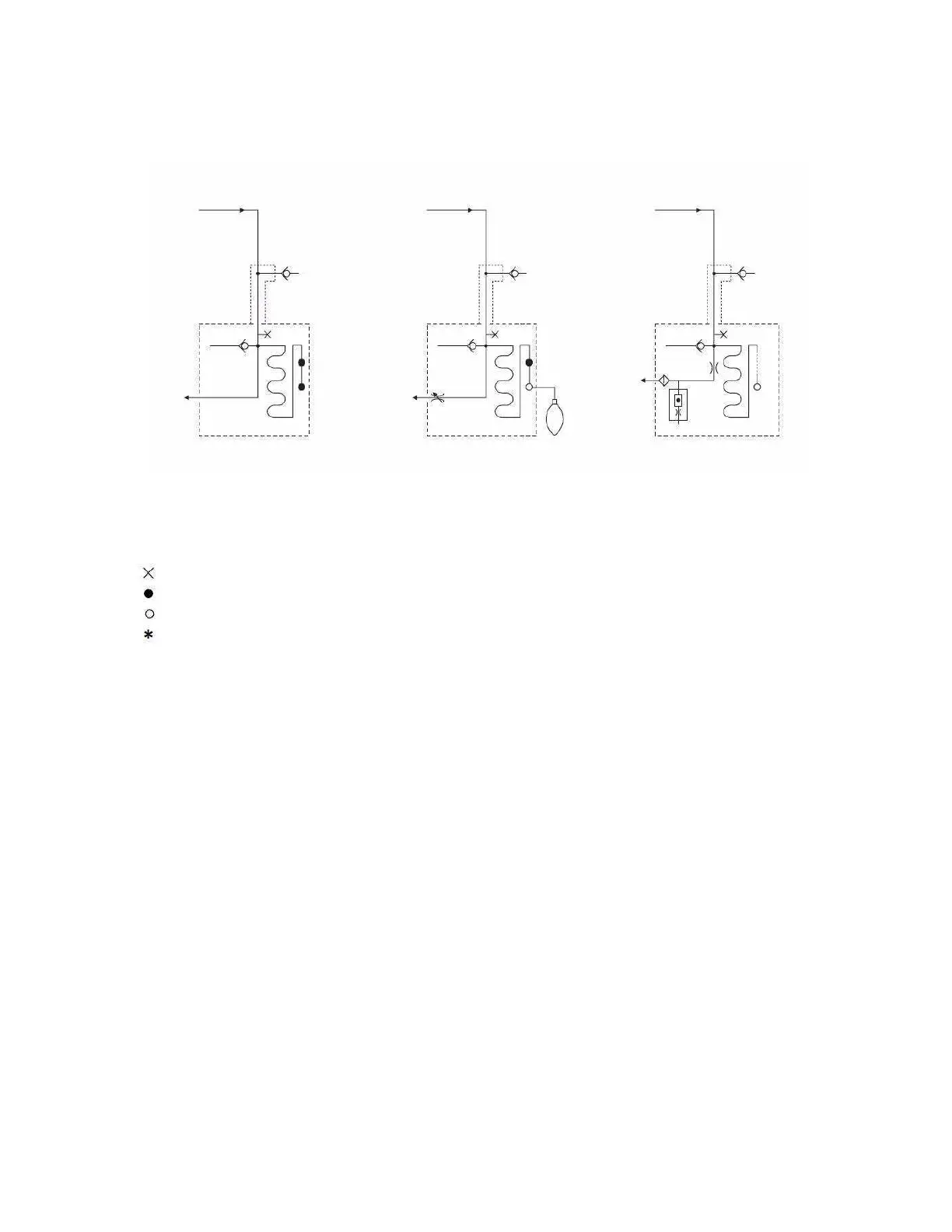
Figure 11-2 • Gas scavenging circuits
Scavenging
From System
*
Scavenging
From System
*
Scavenging
From System
*
+10 cm H
2
O
Relief Valve
+10 cm H
2
O
Relief Valve
+10 cm H
2
O
Relief Valve
0.3 cm H
2
O
Relief Valve
0.3 cm H
2
O
Relief Valve
0.3 cm H
2
O
Relief Valve
30 mm Male
Connector
Needle Valve
Assembly with
DISS EVAC
Connector
High or Low
Flow Connector
to DIsposal System
Passive Adjustable Active
(See Note)
Flow Indicator
Room
Air
Reservoir Reservoir Reservoir
Filter
High or Low
Flow Orifice
Key to Symbols
= Plugged port (1/8 inch) for sample gas return.
= Plugged port (30 mm) for auxiliary breathing system scavenging.
= Open port (30 mm) for auxiliary breathing system scavenging.
= Zero to 10 L/min drive gas; zero to 10 L/min patient and fresh gas; zero to 20 L/min total typical flow.
Note: Active AGSS systems with a 12.7 mm connector do not include the Flow Orifice and the Flow indicator.
M1207027 004 MANUAL−DOC, Technical Reference Manual, Technical Reference Manual for 9100c, English−default
Reproduced from the electronic master in MATRIX