9 Repair Procedure
M1207026 9-15
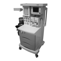
9.8 Replace O
2
supply switch
The O
2
supply switch is located under the tabletop.
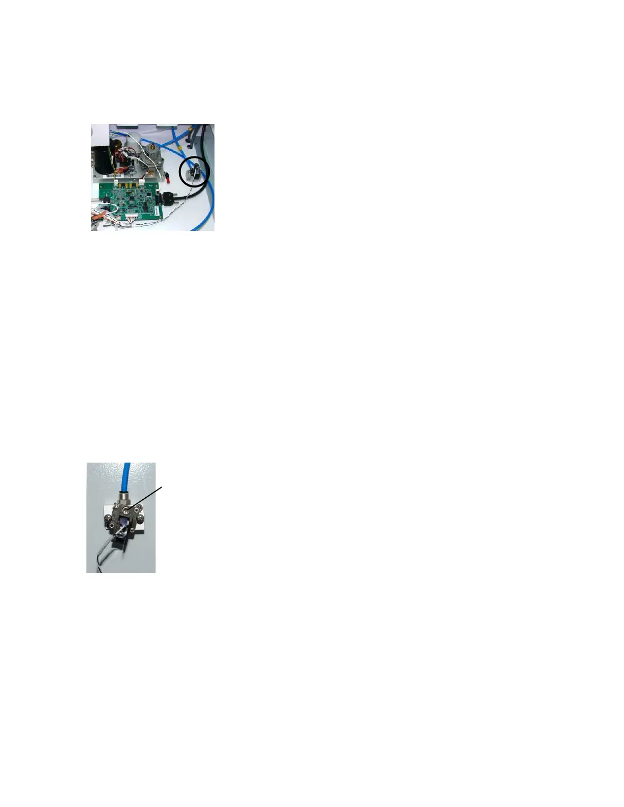
1. Remove the tabletop (Section 9.3).
2. Remove the two mounting screws from the O
2
supply switch.
3. Pull the O
2
supply switch out of the manifold.
4. Install the replacement O
2
supply switch.
5. Tighten the screws.
6. Disconnect the leads from the old switch and reconnect them to
the new switch.
7. Adjust the alarm threshold for the new O
2
supply switch, as
explained in the checkout procedure below (Section 9.8.1).
8. Replace the tabletop.
9. Perform the checkout procedure (Section 3).
9.8.1 Checkout
procedure for O
2
supply switch
1. Remove the tabletop (Section 9.3).
2. Remove the remove the large upper rear panel (Section 9.2).
3. Disconnect all pipeline hoses from the wall and the machine,
close all gas cylinders.
4. Attach a gauge to the O
2
primary regulator test port. (On pipeline
only machines, attach the gauge to a 6-mm O
2
port).
5. Zero the O
2
flow.
6. Install an O
2
cylinder and open the cylinder valve (for pipeline
only, connect O
2
pipeline source).
7. Set the system switch to On.
8. Close the cylinder valve (disconnect pipeline from source) and
watch the test gauge as the O
2
pressure bleeds down slowly.
Note: The “No O
2
pressure” alarm should occur between
descending pressure of 221–193 kPa (32–28 psi).
9. If adjustment is required, set the adjustment screw so that the
“No O
2
pressure” alarm occurs at 207 ±7 kPa (30 ±1 psi).
10. Disconnect the gauge and plug the test port.
11. To reassemble, perform the previous steps in reverse order.
12. Perform the checkout procedure (Section 3).
M1207027 004 MANUAL−DOC, Technical Reference Manual, Technical Reference Manual for 9100c, English−default
Reproduced from the electronic master in MATRIX