9100c
2-20 M1207026
2.7 Electronic and electrical components
2.7.1 9100c ventilator
functional blocks
The 9100c ventilator electronic/electrical subassemblies or modules
includes:
• System switch to set the system to On or Standby;
• Power Supply for operation under line power
and a backup battery for limited operation in case of power
failure;
• Control Sample Board to preprocess patient circuit parameters
and to channel the breathing system switch states.
• Front Panel Assembly that includes an LCD display for display
of all ventilation and monitoring parameters and a keyboard for
operator input;
• Display Monitor Board with digital, and power circuits to
manage all operations of the ventilator;
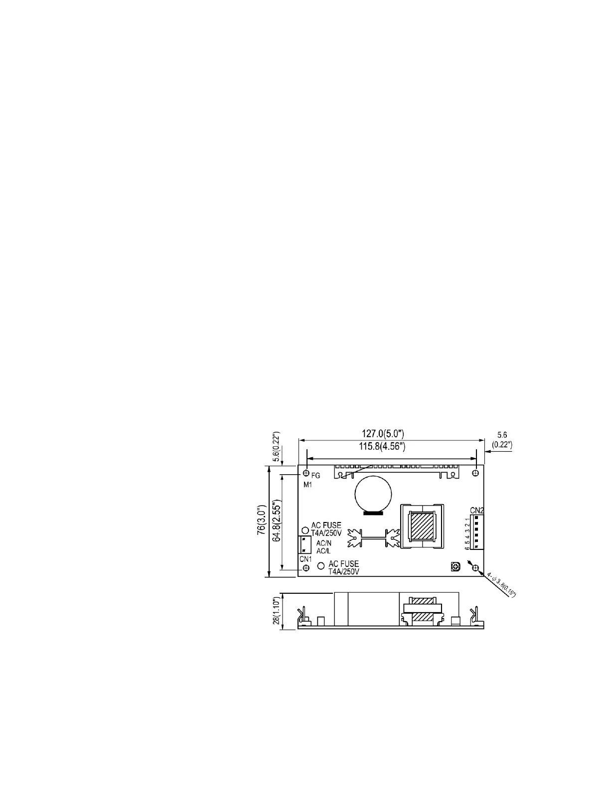
2.7.2 Power supply The power supply receives AC input from the machine’s AC Inlet
Module. The power supply is a universal 45 watt switching supply that
outputs DC voltage. The DC voltage is routed to the Display Monitor
Board where it is further regulated to produce the power requirements
for the 9100c ventilator system.
• Input:
90~264 VAC
•Output:
15.0 VDC (±2%) at 0–3 A
Figure 2-6 • 9100c Ventilator power supply
M1207027 004 MANUAL−DOC, Technical Reference Manual, Technical Reference Manual for 9100c, English−default
Reproduced from the electronic master in MATRIX