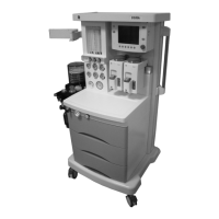
9100c
2-24 M1207026
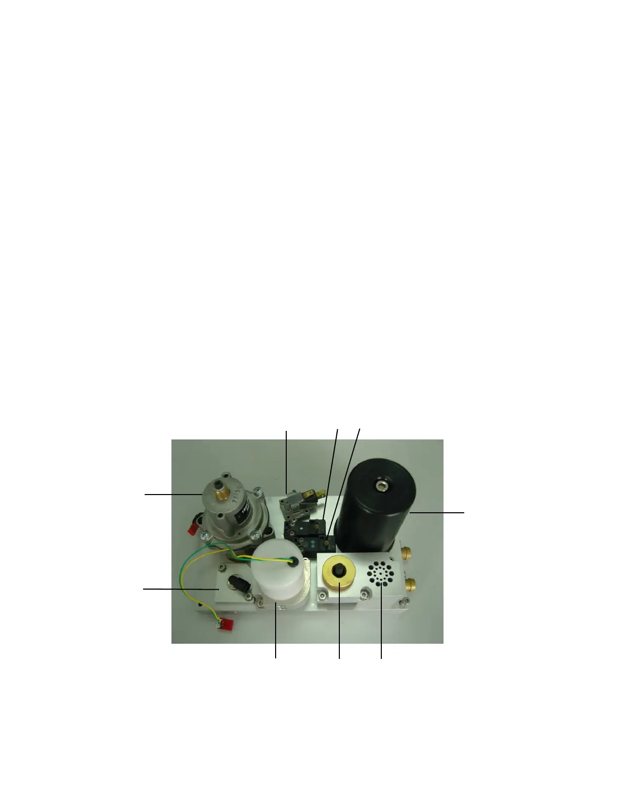
2.8 Ventilator mechanical subsystems
Refer to Figure 2-1, “Pneumatic Circuit Diagram”, in Section 2.2 for
the complete pneumatic/ mechanical subsystem.
The mechanical subsystems include:
Pneumatic Vent Engine
1. Supply gas pressure regulator
2. Drive gas inlet filter
3. Inspiratory flow control valve
4. Mechanical Overpressure Valve (MOPV)
5. Free breathing valve
6. Reservoir and bleed resistor
7. PEEP control valve
8. PEEP safety valve
9. Supply pressure switch
Exhalation valve
Bellows assembly
Breathing circuit flow sensor
Figure 2-9 • 9100c Vent Engine
M1207027 004 MANUAL−DOC, Technical Reference Manual, Technical Reference Manual for 9100c, English−default
Reproduced from the electronic master in MATRIX