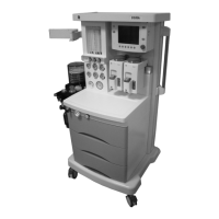
2 Theory of Operation
M1207026 2-5
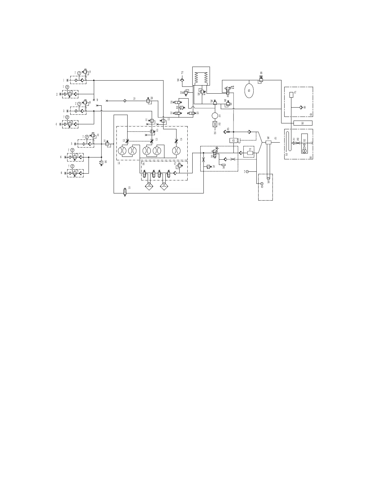
Figure 2-1 • Pneumatic diagram
Key to Numbered
Components
1. Air pipeline inlet 29. Exhalation valve
2. Air cylinder inlet (optional) 30. Scavenging pressure relief valve
3. N
2
O pipeline inlet 31. Reservoir 200 mL
4. N
2
O cylinder inlet (optional) 32. Bleed resistor
5. O
2
pipeline inlet 33. Room air
6. O
2
cylinder inlet (optional) 34. Pressure switch
7. Pressure gauge 35. ACGO select valve
8. Safe pressure relief valve 36. ACGO port
9. Ventilator drive gas select 37. O
2
sensor
10. O
2
supply switch 38. Flow sensor
11. Regulator 39. Flow transducer
12. N
2
O balance regulator 40. Paw sensor
13. Gas throttles 41. Patient lung
14. Flowmeter module 42. Negative pressure relief valve
15. O
2
flush 43. Absorber canister
16. Vaporizer manifold 44. BTV switch
17. 37.9 kPa relief valve 45. Bag
18. Vaporizer 46. APL valve
19. 0-120 L/min flow 47. 30mm-connect scavenging system
20. Regulator 48. 0.05 kPa inlet
21. PEEP safety valve 49. Passive AGSS interface
22. Pressure sense switch 50. Scavenging base
23. PEEP control valve 51. Filter
24. Inspiratory flow valve 52. High or low restrictor
25. Mechanical overpressure relief 53. Flow indicator
26. Free breathing check valve 54. To disposal system
27. Atmosphere 55. Active AGSS interface
28. Pop-off valve
M1207027 004 MANUAL−DOC, Technical Reference Manual, Technical Reference Manual for 9100c, English−default
Reproduced from the electronic master in MATRIX