5-7
Chapter 5 Specification
Contents General Description
Checks and Preparation
Settings and Measurement
Example of Use Specification
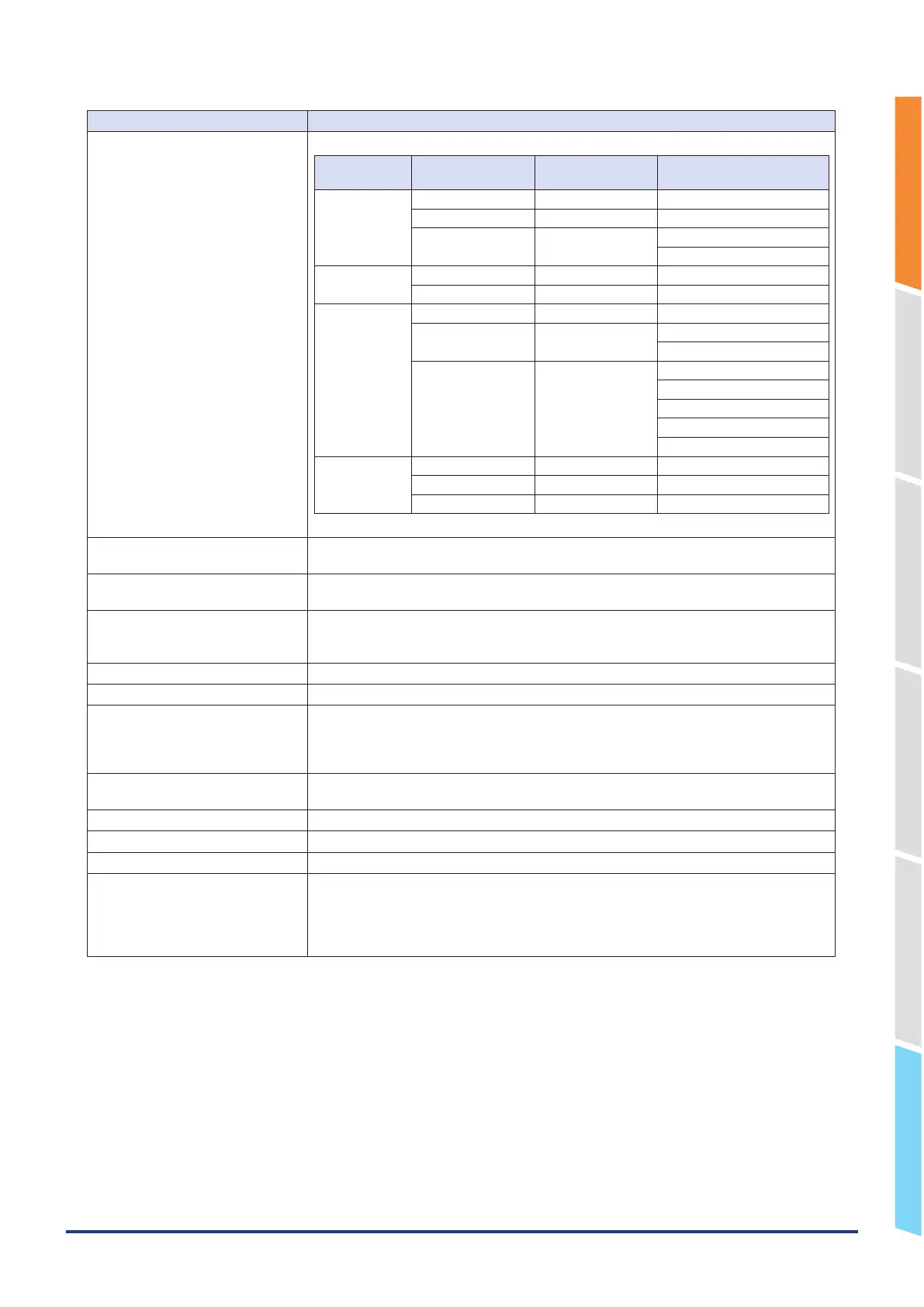
Item Description
• Temperature range
Type
Temperature
range
Resolution Measurement Range
R/S 100℃ F.S. 0.01℃ 0 to 100℃
500℃ F.S. 0.05℃ 0 to 500℃
2000℃ F.S. 0.1℃ R : 0 to 1600℃
S : 0 to 1760℃
B 500℃ F.S. 0.05℃ 400 to 500℃
2000℃ F.S. 0.01℃ 500 to 1820℃
K/E/T/J/N 100℃ F.S. 0.01℃ -100 to 100℃
500℃ F.S. 0.05℃ K/E/J/N: -200 to 500℃
T: -200 to 400℃
2000℃ F.S. 0.1℃ K: -200 to 1370℃
E: -200 to 800℃
T: -200 to 400℃
J: -200 to 1100℃
N: -200 to 2000℃
C (W) 100℃ F.S. 0.01℃ 0 to 100℃
500℃ F.S. 0.05℃ 0 to 500℃
2000℃ F.S. 0.1℃ 0 to 2000℃
* Measurement accuracy does not change due to the temperature range.
Reference contact compensation
accuracy
Internal/External switching
A/D converter Method: ΔΣ method
Resolution: 16-bit (Effective resolution: About 1/40000 of the +/– range)
Temperature coefficient Gain: 0.01% of F.S./°C
Zero: 0.02% of F.S./°C
* Zero occurs at the sampling of 5, 10, 20, and 50 ms.
Input resistance 1MΩ ±5%
Allowable signal source resistance Within 300Ω
Maximum permissible input voltage Between +/– terminals: 20mV to 2V range (60Vp-p)
5V to 100V range (110Vp-p)
Between input terminal/input terminal: 60 Vp-p
Between input terminal/GND: 60 Vp-p
Withstand voltage Between input terminal/input terminal: 350 Vp-p 1 minute
Between input terminal/GND: 350 Vp-p 1 minute
Insulation resistance Between input terminal/GND: 50MΩ or more (at 500 VDC)
Common mode rejection ratio 90 dB or more (50/60 Hz; signal source 300Ω or less)
Noise 48 dB or more (with +/– terminals shorted)
Filter Off, 2, 5, 10, 20, 40
Filter operation is on a moving average basis.
The average value of the number of set samples is used.
If the sample interval exceeds 30 seconds, the average value of data obtained in a sub-
sample (30 seconds) is used.