2-19
CHAPTER 2 Checks and Preparation
Contents General Description
Checks and Preparation
Settings and Measurement
Example of Use Specification
2.8
Logic Alarm Cable Connection and Functions
This section describes how to connect the logic alarm cables and the functions of cable.
During wiring, confirm that the signal’s supply source is turned OFF to prevent electrical shocks.
Also, position the GL860 input cable away from any power lines and ground cables.
CAUTION
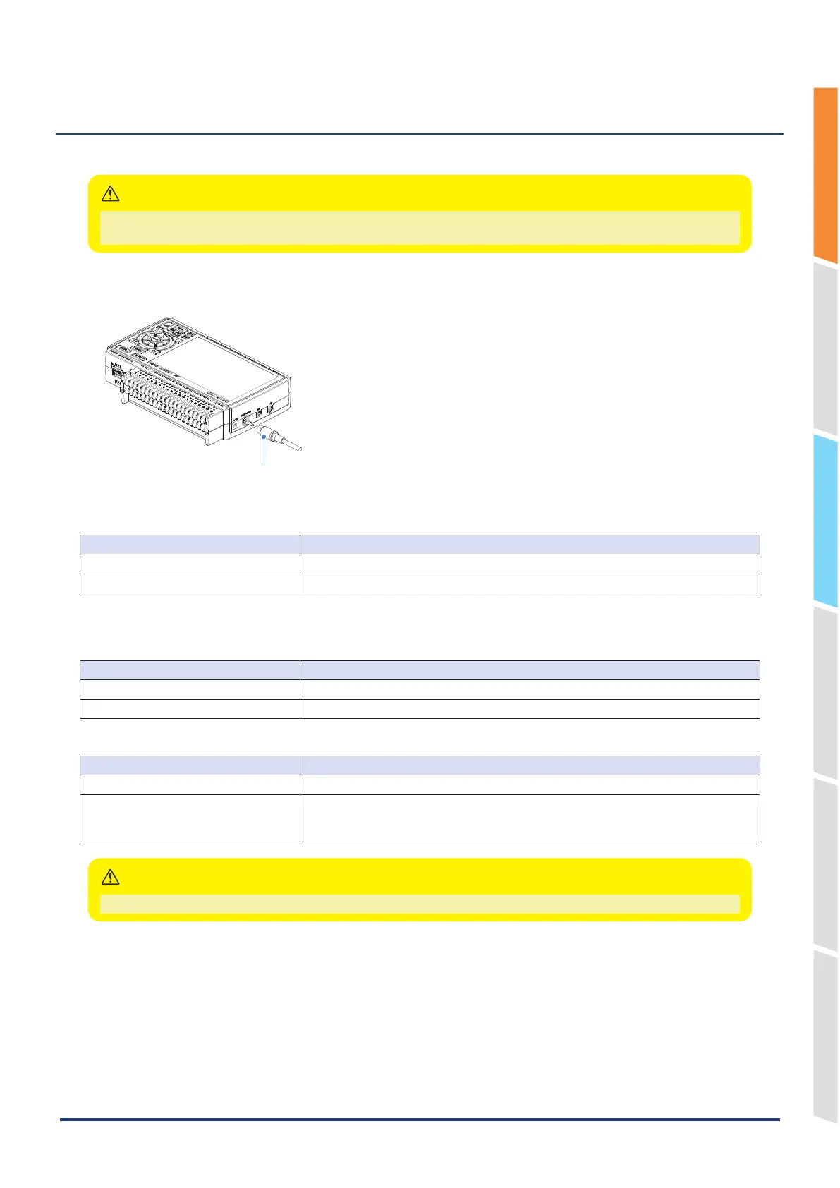
The Input/output cable for GL (B-513: Option) enables logic/pulse input, external trigger input, and alarm signal output.
Connect the Input/output cable for GL (B-513: Option) to the external input/output terminal as shown below.
Input/output cable for GL
(B-513: Option)
Logic/Pulse Input Specifications
Item Description
Number of input channels 4
Input voltage range 0 to +24 V max. (single-ended ground input)
* Switch between logic and pulse input.
Trigger Input/External Sampling Input Specifications
Item Description
Number of input channels 1
Input voltage range 0 to +24 V max. (single-ended ground input)
Alarm Output Specifications
Item Description
Number of Output channels 4
Output format Open collector output
+5 V, 10 KΩ pull-up resistance
* See the next page for details on alarm output
When the power is turned OFF or ON, the GL860 temporarily becomes the alarm state.
CAUTION