2-14
CHAPTER 2 Checks and Preparation
Contents General Description
Checks and Preparation
Settings and Measurement
Example of Use Specification
2.7 Connecting the Signal Input Cables
This section describes how to connect the signal input cables.
During wiring, confirm that the signal’s supply source is turned OFF to prevent electrical shocks.
Also, position the GL860 input cable away from any power lines and ground cables.
CAUTION
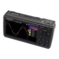
Terminal Configuration and Signal Types (Standard 20CH screw terminal: B-563)
CH20 CH1
+
-
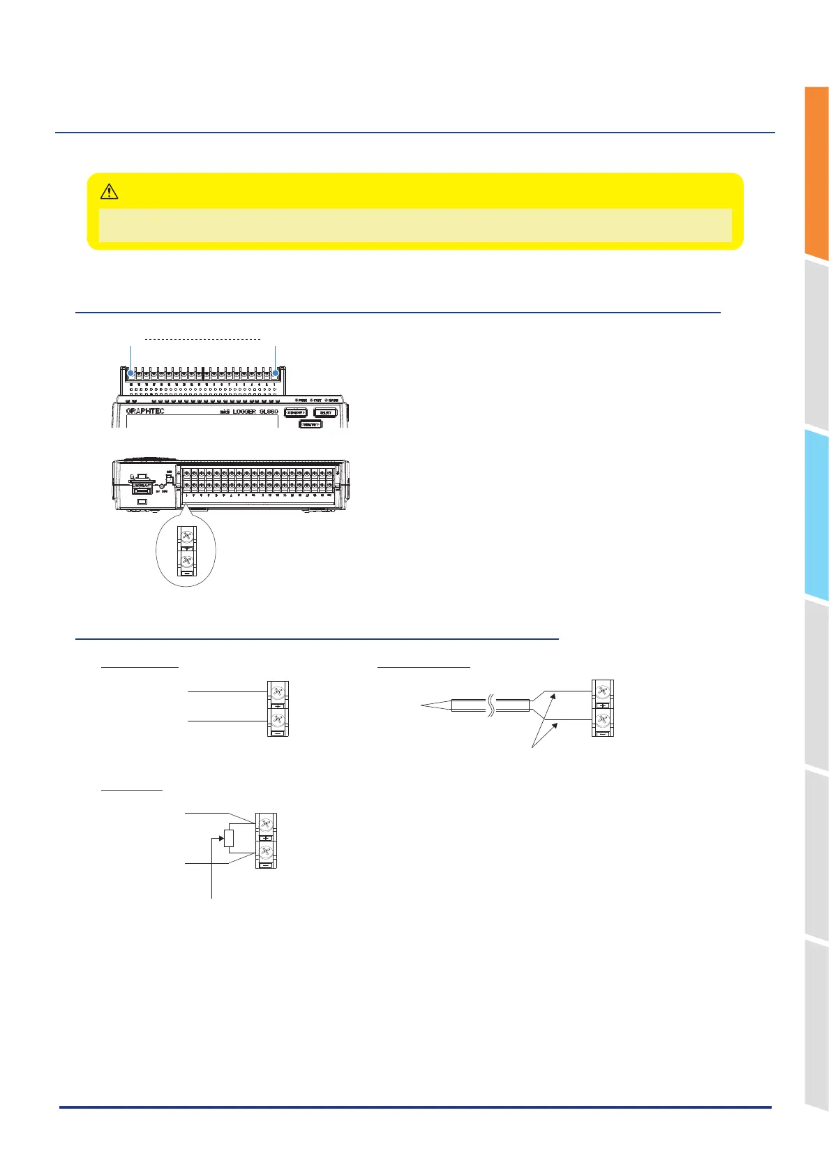
Connection diagram (Standard 20CH screw terminal: B-563)
+
-
+
-
+
-
DC voltage input Thermocouple input
Current input
Voltage input
Compensation copper wire
Shunt resistor
Ex: The current is converted to the voltage in the shunt resistor.
For 4 to 20mA current input, installing 250 ohms (0.1%) resistor for converting 1 to 5V.
* Use B-551 (option) for the shunt resistor.
+ ...................High-voltage terminal (terminal for high-voltage input signals)
– ...................Low-voltage terminal (terminal for low-voltage input signals)