3-2
Chapter 3 Settings and Measurement
Contents General Description
Checks and Preparation
Settings and Measurement
Example of Use Specification
3.1
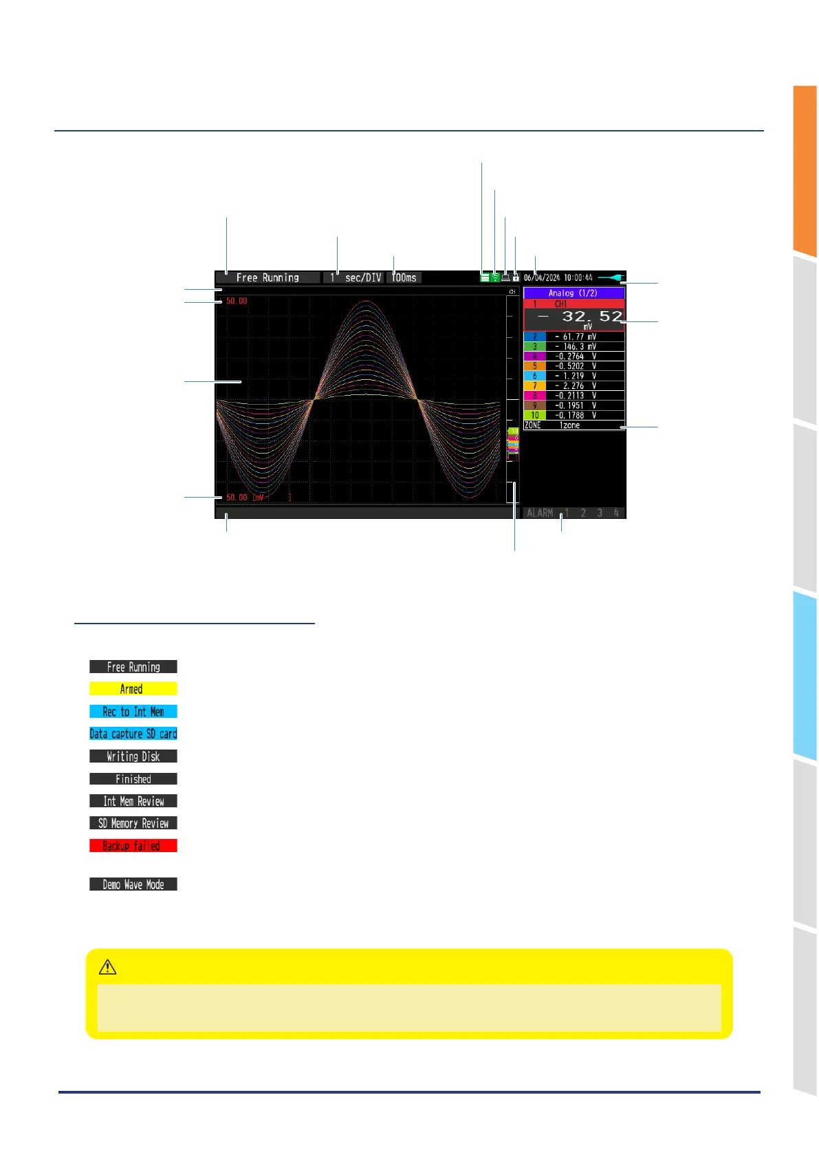
Name of each screen part and functions
1. Simplified message display
2. TIME/DIV
3. Sampling interval
4. Device access display
(Internal memory)
5. Device access display
(SD memory card / wireless LAN display)
6. Remote lamp
7. Key lock display
8. Clock display
9. AC/Battery status
indicator
10. Digital display area
11. Quick settings
12. Alarm display area
13. Pen display
14. File name display area
15. Scale lower limit
16. Waveform display
area
17. Scale upper limit
18. Data capture bar
1. Simplified message display
Displays the operation status of the GL860.
: Appears in the start-up status or when data is not being captured.
: Appears while waiting for trigger generation after the measurement is started.
* : Displayed when the data is captured to the internal memory.
* : Displayed when the data is captured to the SD memory card.
* : Displayed when performing the capturing stop process.
: Appears when the GL860 waits for you to press the [START/STOP] key to stop it after data capture.
* : Displayed when the data in the internal memory is replayed.
* : Displayed when the data in the SD memory card is replayed.
: Appears when backup fails (e.g. when the SD memory card specified as the backup destination
has been removed).
: Appears when a demo waveform is being displayed, not measurement data.
*
Refer to "3. TRIG settings" in "3.4 Setting Menus" for details on the data capture such as a trigger and repeat.
* Refer to "2-4. Captured data file name" in "3.4 Setting Menus" for details on data capture settings.
Please do not turn off the power when the “ * “ status icon is displayed or the device is being accessed.
The data that has been captured or is being captured may be damaged.
Make sure the status message is “free running” before performing the next operation.
CAUTION