2-17
CHAPTER 2 Checks and Preparation
Contents General Description
Checks and Preparation
Settings and Measurement
Example of Use Specification
Item Description
Input configuration Isolated input, scanning
Measurement range 20, 50, 100, 200, 500 mV/F.S.; 1, 2, 5, 10, 20, 50, 100 V; 1-5V/F.S.
Thermocouples K, J, E, T, R, S, B, N, C (W: WRe 5-26)
A/D resolution 16-bit (Effective resolution: Approx. 1/40,000 of the +/- range)
Filter Off, 2, 5, 10, 20, 40
Filter operation is on a moving average basis.
The average value of the set sampling count is used.
If the sample interval exceeds 30 seconds, the average value of data obtained in a
sub-sample (30 seconds) is used.
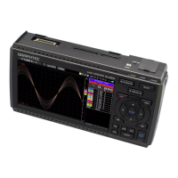
Terminal Configuration and Signal Types
(Withstand high-voltage high-precision terminal:B-565)
CH20 CH1
+
-
b
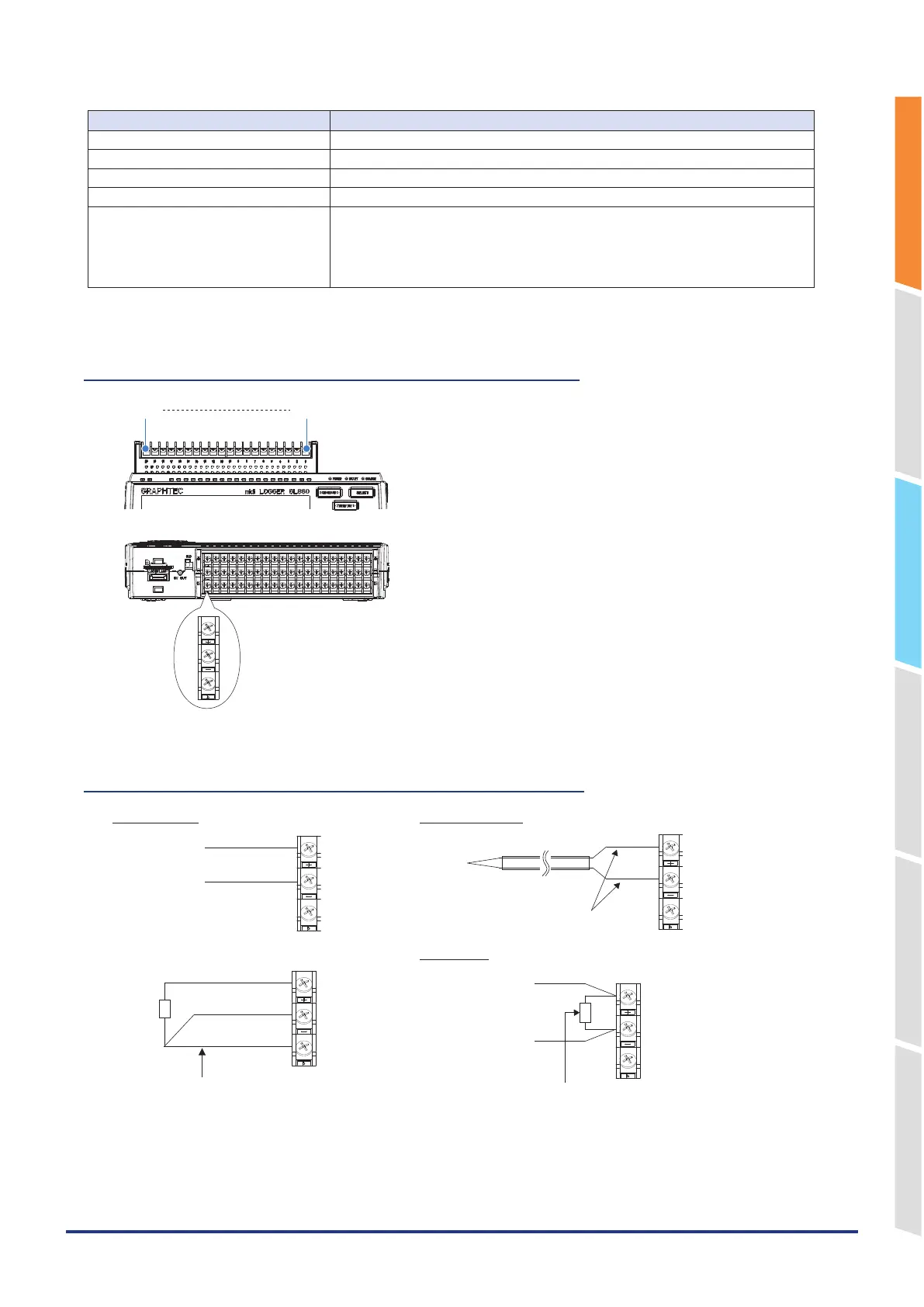
Connection diagram
(Withstand high-voltage high-precision terminal: B-565)
-
B
b
+
-
b
-
-
DC voltage input Thermocouple input
*Use B-551 (option) for the shunt resistor. Current input
Voltage input
Compensation copper wire
The lead wire resistance per line should
be 10Ω or less, and the resistance values
of the three lines should be equal.
Shunt resistor
Ex: The current is converted to the voltage in the
shunt resistor.
For 4 to 20mA current input, installing 250 ohms
(0.1%) resistor for converting 1 to 5V.
* Use B-551 (option) for the shunt resistor.