2-18
CHAPTER 2 Checks and Preparation
Contents General Description
Checks and Preparation
Settings and Measurement
Example of Use Specification
+ ...................High-voltage terminal (terminal for high-voltage input signals)
– ...................Low-voltage terminal (terminal for low-voltage input signals)
b ②②②②②②②②②②②②②②②②②②②②②②②②②②②②②②②②②②②②② ...................Dedicated terminal when connecting resistance bulb
* Resistance bulb input terminals A (+) and B (-) are isolated within each channel. Terminal b is shorted within all
channels.
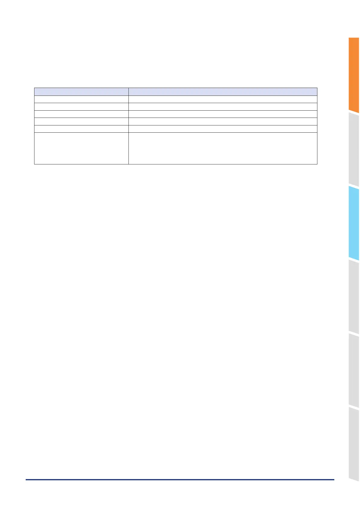
Item Description
Input configuration Isolated input, scanning
Measurement range 20, 50, 100, 200, 500 mV/F.S.; 1, 2, 5, 10, 20, 50, 100 V; 1-5V/F.S.
Thermocouples K, J, E, T, R, S, B, N, C (W: WRe 5-26)
Resistance bulb Pt100, JPt100, Pt1000 (IEC751)
A/D resolution 16-bit (Effective resolution: Approx. 1/40,000 of the +/- range)
Filter Off, 2, 5, 10, 20, 40
Filter operation is on a moving average basis.
The average value of the set sampling count is used.
If the sample interval exceeds 30 seconds, the average value of data obtained in a
sub-sample (30 seconds) is used.