2-10
CHAPTER 2 Checks and Preparation
Contents General Description
Checks and Preparation
Settings and Measurement
Example of Use Specification
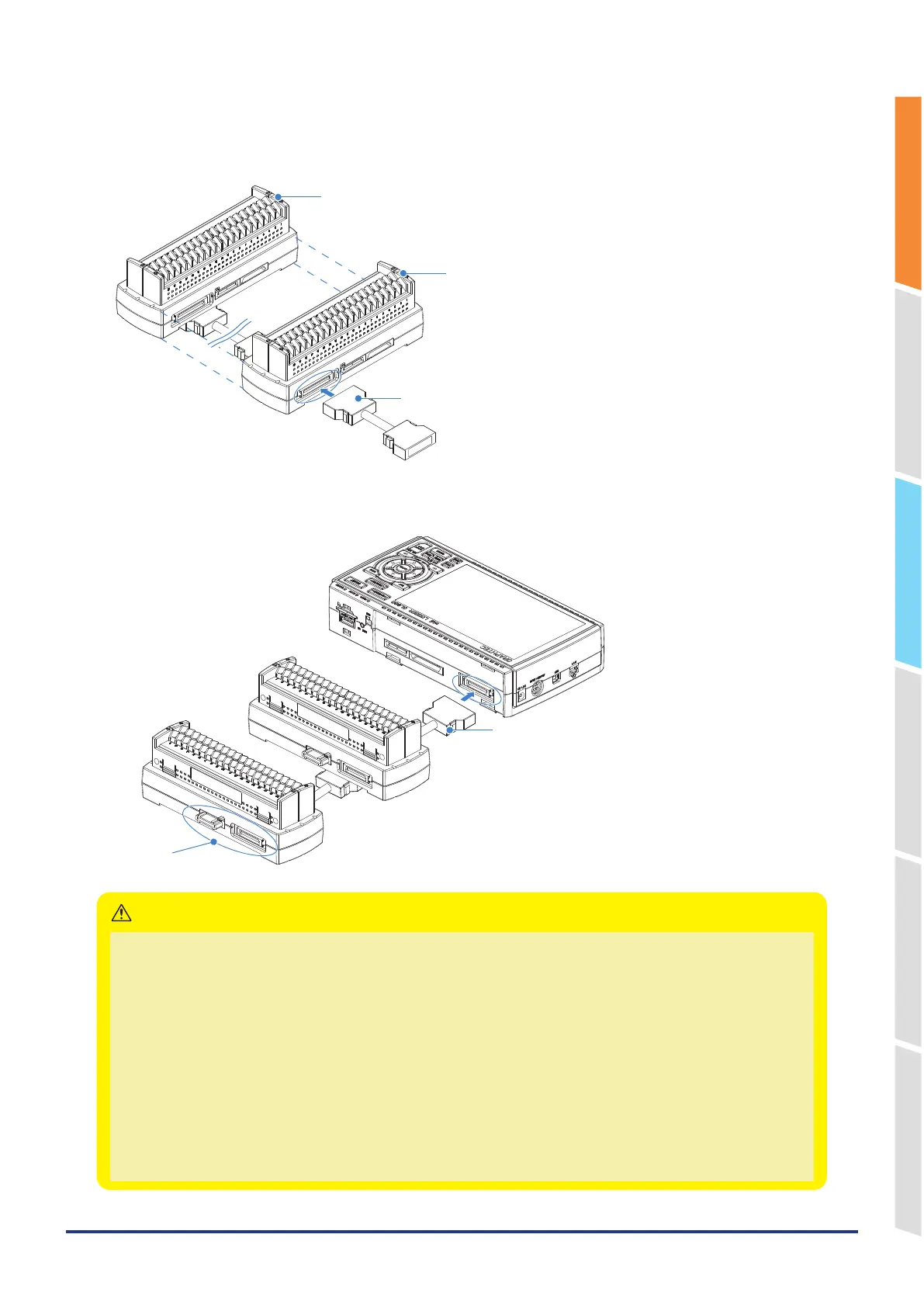
2. Connect each between the extension terminal bases with the extension terminal connection cable.
* Insert the extension terminal connection cable until the cable is securely locked.
Install the extension terminal bases in a stable location and be careful not to fall.
Unit 1 (CH1 to CH20)
Unit 2 (CH21 to CH40)
Extension terminal connection cable
3. Connect one end of the extension terminal connection cable to the GL860.
* Insert the extension terminal connection cable until the cable is securely locked.
Extension terminal connection cable
Do not touch.
• While the signal is input to the direct-connected terminal, please do not touch the connector pins and terminal next to the
connector.
• When removing the extension terminal connection cable from the GL860 or the extension terminal base, please note the
following:
• Please always pull out straightly in a state where both sides of the lock release lever are pushed.
• Please do not forcibly remove or do not pull out in a state where only one side of the lock release lever is pushed.
It may cause a connection failure of the connector, please be careful when you remove it.
• When the extension terminal cable is used, it becomes susceptible to noise.
• When the combination of the Standard 20CH screw terminal and Withstand high-voltage high-precision terminal is used,
the withstand voltage specification of the standard terminal is applied.
• When using a Standard 30CH screwless terminal in combination, terminals connected across 200CH will not be
recognized.
Example: When 190CH is implemented with eight Standard 20CH screwless terminals and one Standard 30CH screwless
terminal, even if an additional Standard 20CH screwless terminal is installed, the total will be 210CH, so the additional
terminal will not be recognized.
CAUTION