2-33
CHAPTER 2 Checks and Preparation
Contents General Description
Checks and Preparation
Settings and Measurement
Example of Use Specification
GND
+
-
+
-
+
-
B
B
C
C
A
GND
+
-
+
-
+
-
C
B
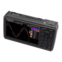
[ Temperature measuring ]
Thermocouple
Thermocouple
Thermocouple
[ Voltage measuring ]
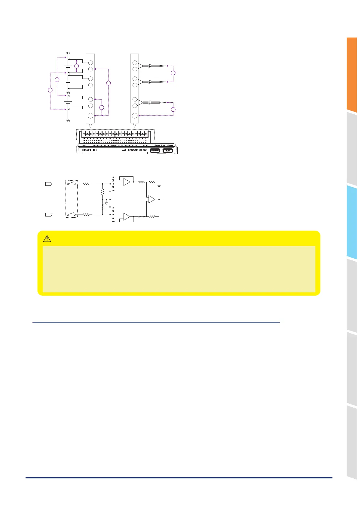
Input Circuit Diagram for Analog Input (Voltage, Thermocouples)
50Ω
50Ω
500kΩ
500kΩ
0.05μF
0.05μF
+
-
Channel Switching Relay
Capacitors have been incorporated into the input circuit to increase the noise-elimination capability.
After voltage measurement, when the inputs have been disconnected, there will still be some electric charge remaining.
Before starting another measurement operation, short-circuit the + and – terminals to enable self-discharge.
The GL860 has a scan system.
While in the status (open) in which signals are not input to the input terminal, measured results may be influenced by
signals from other channels. In such a case, turn OFF the input setting or short circuit +/–.
If signals are input correctly, measured results are not influenced by other channels.
CAUTION
When using the Withstand high-voltage high-precision terminal (B-565)
Maximum input voltage
If a voltage exceeding the specified value is input, the semiconductor relay in the input section will be damaged.
Never input a voltage exceeding the specified value even for a moment.
* This applies to all the channels even if channel extension is used.
< Between +/– terminals (A) >
Maximum input voltage: 60Vp-p (Range of 20mV to 2V)
110Vp-p (Range of 5V to 100V)
<Between input terminal/input terminal (B) >
Maximum input voltage: 600Vp-p
Withstand voltage: 600Vp-p
<Between input terminal/GND (C) >
Maximum input voltage: 300Vp-p
Withstand voltage: 2300Vp-p at 1 minute