41 / 116
S1002.PRO_mz12PRO_Teil2_V1sh
Control setting
Select the desired menu using the selection buttons and then press
the ENT button to enter the setup page of the menu.
Push the ESC key to stop the procedure.
The control channels 1 ... 4 are assigned to the stick control func-
tions, which is why only the control channels 5 ... 12 can be assigned
to other control elements of the transmitter.
Note for helicopter
In contrast to the designations E6, E7 and E12 of the displays of the
four other model types shown in this section, the inputs are desig-
nated as Throttle, Gyr and Lim. The special requirements of these
three inputs are discussed at the end of this section.
Programming step-by-step
1. Use the selection buttons to select the input to be set and, if nec-
essary, the value field to be set.
2. Push the ENT key.
3. Use the selection keys to set the desired value.
4. Press the ENT key to complete the operation.
5. Proceed appropriately with the remaining value fields.
6. Push the ESC key to stop the procedure.
Column "Control"
The required switch or rotary control is assigned in this column.
The assignment takes place as described in the section "Control,
switch and transmitter switch assignment".
Notes
• Even if misused, an unnecessary control element will not influ-
ence the model if it remains inactive, that is, when it has not
been assigned a function.
• Settings in this menu affect all mixing and coupling functions
that may be output, and thus ultimately to all RC components
which are actuated via the related control element.
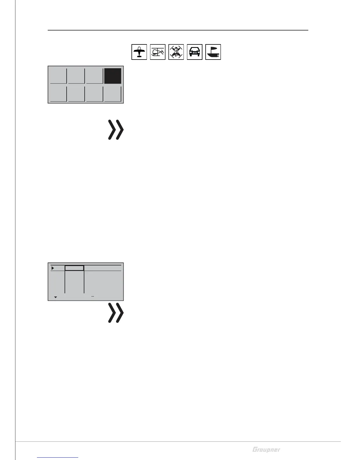
Model
memory
D/R
Expo
Tx
setting
Wing
mix
M.Type
Phase
Servo
setting
Ctl
setting
C1
curve
E5
E6
+
Trv
+100%
+100%
+100%
+100%
free
free
E7
+100%
+100%free
E8 +100%
+100%
free
E9 +100%
+100%free
 Loading...