57 / 116
S1002.PRO_mz12PRO_Teil2_V1sh
Helicopter mixer
Select the desired menu using the selection buttons and then press
the ENT button to enter the setup page of the menu.
Push the ESC key to stop the procedure.
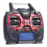
Helicopter mixer description
For the settings of the control curves of "Pitch", "C1 => Thr" and "C1
=> Tail", 5-point curves are available. Also in this mixer can however
only be programmed if required not linear mixer actions analogue to
the control stick travels. In the "Autorotation" phase, on the other
hand, the mixers "C1 => Thr" and "C1 => Tail" are not required and
are therefore switched to an adjustable default value.
In the "Gyro" line, a value must be entered, analogous to the control
centre adjustment or offset setting of other remote control systems.
These setting options are rounded off with the "SP limit" option:
Depending on the setting, this limits the maximum swing-out of the
swash plate servos in the manner of a limiter.
If phases are provided with switches, the name of the respectively
selected phase, e. g. "normal", in the "Heli mix" menu as well as in
the base display of the transmitter. However, the change between
the phases is not "hard" on the servo side, but with a fixed switching
time of approx. 1 second. Only IN the autorotation phase is switched
immediately.
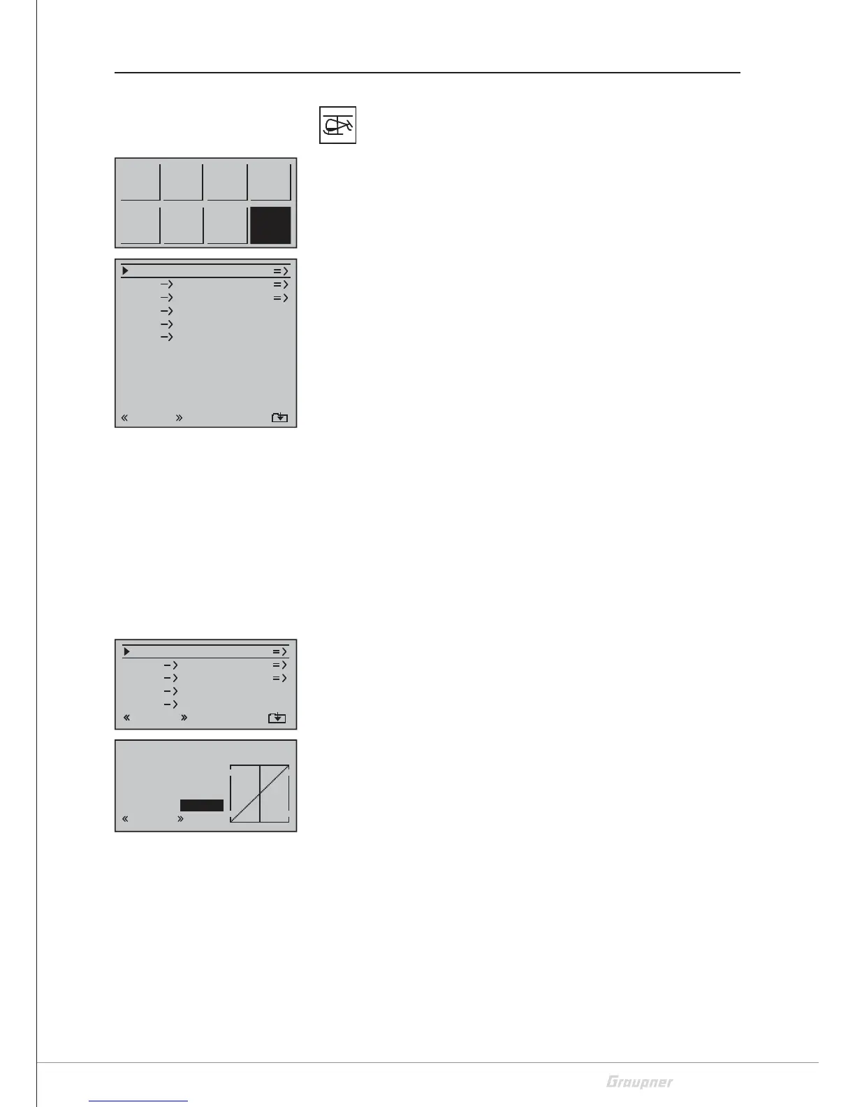
Pitch
The control curve can be specified by up to 5 points, termed support
points in the following, along the entire control stick travel: The
graphic display makes it much easier to specify the support points
and their adjustment. It is, however, recommendable to start with
just a few support points.
Use the control element to move a vertical green line between the
two endpoints "Point1" and "Point5" in the graphic. The momentary
control stick position is displayed numerically in the line "Input". The
intersection of this mixer support line with the curve is identified as
"Output" and can be varied at the support points between -125%
and +125%.
Between the two endpoints, "point1" at -100% and "point5" at
+100% of the control travel, up to three additional points can be
defined at -50%, 0% and +50% of the control travel.
Setting or changing the support point step-by-step
1. Push the ENT key to change from the selection list to the "Pitch"
setting page.
2. Move the CH1 control stick to the desired position.
ModEL
memory
D/R
Expo
Tx
setting
Ctl
setting
Servo
setting
Heli
Mixer
M.Type
Phase
C1
curve
C1
C1
Pitch
Thr
Tail
Tail
0%
Roll 0%
Thr
Thr
Nick
Thr
Sp limit
0%
OFF
normal
Gyro
0%
ESC at C8
no
ESC setting
50%
Gyro suppression
0%
Input
Output
Point3
0%
0%
Pitch
normal
+100%
C1
C1
Pitch
Thr
Tail
normal
0%
SEL
0%Tail
Thr
Thr
Roll
 Loading...