52 / 116
S1002.PRO_mz12PRO_Teil2_V1sh
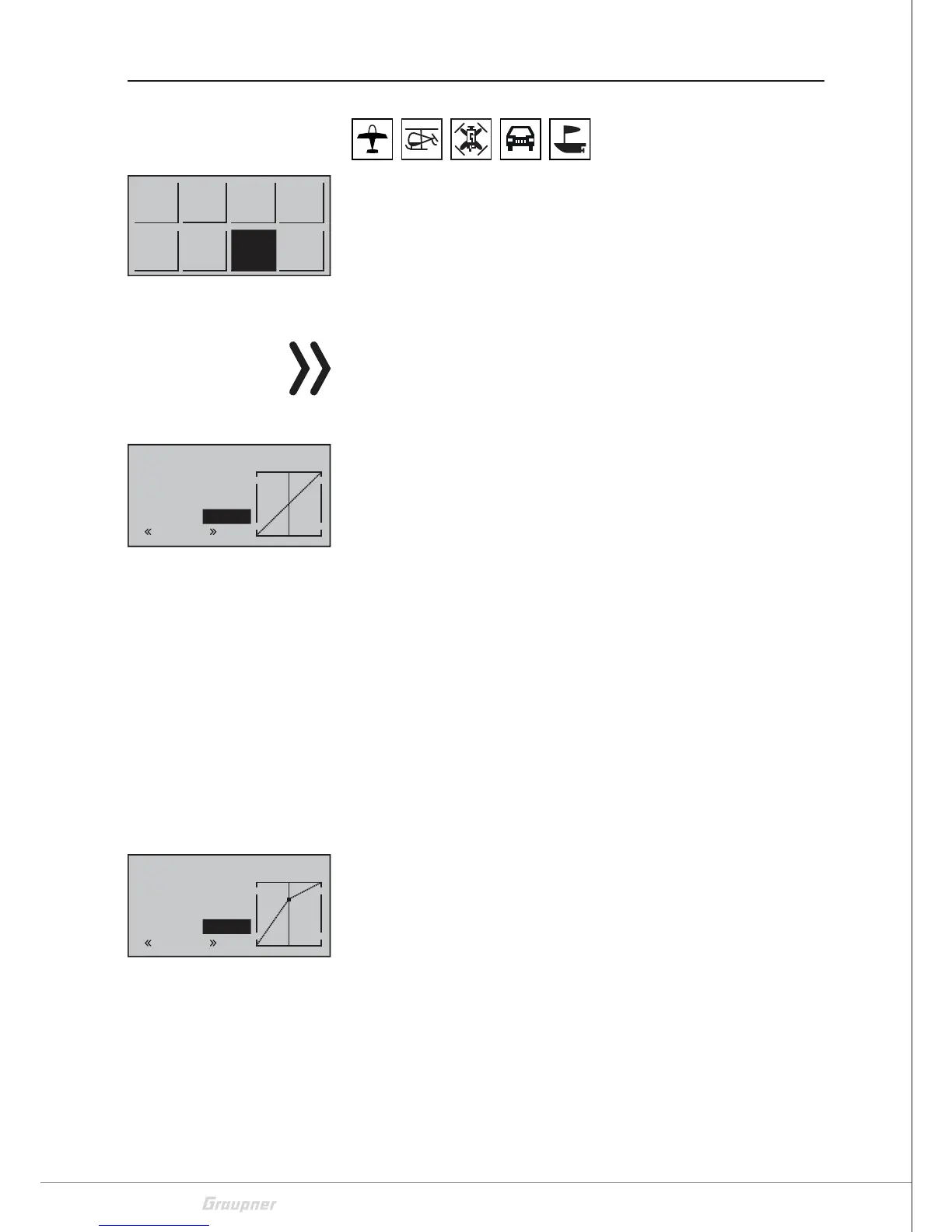
Throttle curve
Select the desired menu using the selection buttons and then press
the ENT button to enter the setup page of the menu.
Push the ESC key to stop the procedure.
Regardless of whether the CH1 control stick is acting directly on the
corresponding RC component or via several mixers on several com-
ponents, the control characteristics of the throttle / brake or pitch
control stick can be changed with this option.
Note for helicopter
The curve characteristic set here also acts as an input signal to the
"Pitch", "CH1 => Thr" and "CH1 => Tail" options of the "Helicopter
Mix" menu.
If phases have been provided with switches, this option may have to
be adjusted phase-dependent. The respective phase name is dis-
played in the lower left corner of the display, e.g. "normal".
The control curve can be specified by up to 5 points, termed support
points in the following, along the entire control stick travel: The
graphic display makes it much easier to specify the support points
and their adjustment. It is, however, recommendable to start with
only three support points.
Use the control element to move a vertical green line between the
two endpoints "Point1" and "Point5" in the graphic. The momentary
control stick position is displayed numerically in the line "Input". The
intersection of this mixer support line with the curve is identified as
"Output" and can be varied at the support points between -125%
and +125%.
Between the two endpoints, "point1" at -100% and "point5" at
+100% of the control travel, up to three additional points can be
defined at -50%, 0% and +50% of the control travel.
Setting or changing the support point step-by-step
1. Move the CH1 control stick to the desired position.
2. Use one of the selection buttons to set the desired value or acti-
vate the point and then set the value.
3. Proceed in the same way with the remaining points.
4. Leave the menu pushing the ESC key.
Deleting the support point step-by-step:
1. Move the CH 1 control stick to the point to delete.
2. Push simultaneously the left and the right selection keys.
3. Close the menu pushing the ESC key.
Model
memory
D/R
Expo
Tx
setting
Ctl
setting
Servo
setting
Wing
mix
M.Type
Phase
C1
curve
Input
Output
Point3
0%
0%
C1
curve
normal
deact
Input
Output
Point3
0%
0%
C1
Normal
curve
normal
+50%