GEN7iB
133
DIGITAL TRIGGER MODES
DIGITAL TRIGGER MODES
10
10.2 Understanding digital triggering
Technicallyspeaking,therearetwoapproachestodeterminetheknown,predened
situation of the signal: analog or digital.
Each channel in the GEN series system is equipped with a digital trigger detector. Digi-
taltriggeringhasthebenetofstableverticalreferencelevels,nohorizontaljitter,and
not depending on signal frequency.
A disadvantage of a digital trigger detector is its inability to detect events that occur
between two consecutive samples. This does not usually interfere with normal opera-
tion because the event is not recorded anyway.
10.2.1 Digital trigger detector
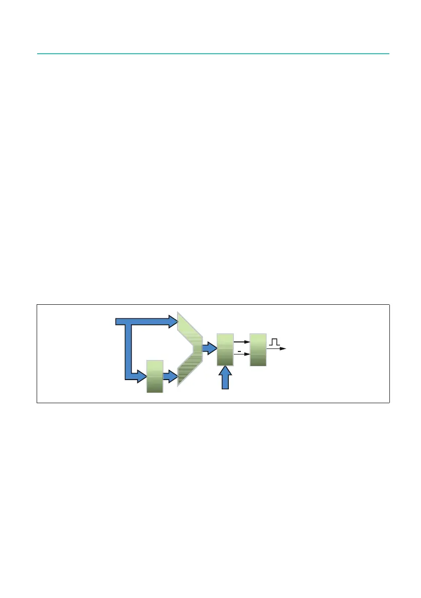
Fig.10.1showsasimplieddiagramofasingle-level digital trigger detector. Digitized
values coming from the ADC are fed into an Arithmetic (and) Logic Unit – ALU. The
value that comes out of the ALU is then referenced against a preset value (trigger
level). The result can be either positive, i.e. the value is larger, or negative, i.e. the value
issmaller.Basedonthisinformation,thelevelcrossingdetectorveriesifalevel
crossing in the correct direction has occurred and, if so, sends out a trigger.
7ULJJHU
/HYHOFURVVLQJ
GHWHFWHG
'(/$<
$/8
Fig. 10.1 Single-level trigger detector
The delay register in front of the ALU is used to compare the ADC value with “older”
values.Thismeansthattriggeringdoesnotreacttospeciclevels,buttothedifferen-
tial signal or slope.
As explained later in this chapter, a signal must actually cross the preset level. This is
to avoid erroneous triggering due to a small amount of noise on the signal. To make
the trigger detector even more stable when noisy signals are used, the single-level
trigger detector has been expanded with a hysteresis. After the level detector signals
alevelcrossing,anewlevelcrossingwillonlybesignalediftheinputsignalrstgoes
outside the hysteresis band and then returns to the trigger level.

 Loading...