GEN7iB
240
INPUT CARDS
INPUT CARDS
12
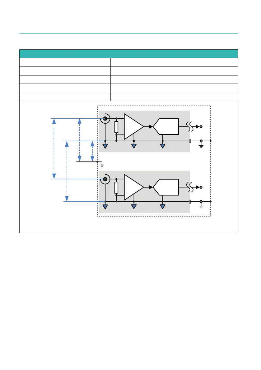
Limit for safe voltage and currents (GN815 and GN816)
Input signal to input signal ± 140 V DC, 55 V RMS (low voltage limit)
Input signal-to-chassis ± 70 V DC, 33 V RMS (low voltage limit)
Channel to chassis ± 70 V DC, 33 V RMS (low voltage limit)
Channel to channel ± 70 V DC, 33 V RMS (low voltage limit)
Nondestructive, to chassis (earth) ± 70 V DC, 33 V RMS AC (low voltage limit)
Ͳ
н
$'&
,VRODWHGFKDQQHO
Ͳ
н
$'&
,VRODWHGFKDQQHO
&KDVVLV
9506
9'&
9506
9'&
9
506
9'&
9
506
Fig. 12.57 Isolation of the Isolated Basic card (GN815/GN816)
12.4.5 Understanding the GN815 and GN816 input
The isolation of the GN815's and GN816's signal input channels are single-ended (also
termed unbalanced isolated or unbalanced differential isolated).
This means that one signal of both inputs within one channel pair is directly connected
to the isolated channel ground (this is the outer signal of the BNC plug). The other
signalisconnectedtotheconditioningamplier.
A(simplied)schematicrepresentationoftheinputchanneloftheGN815andGN816
can be found below.

 Loading...