GEN7iB
230
INPUT CARDS
INPUT CARDS
12
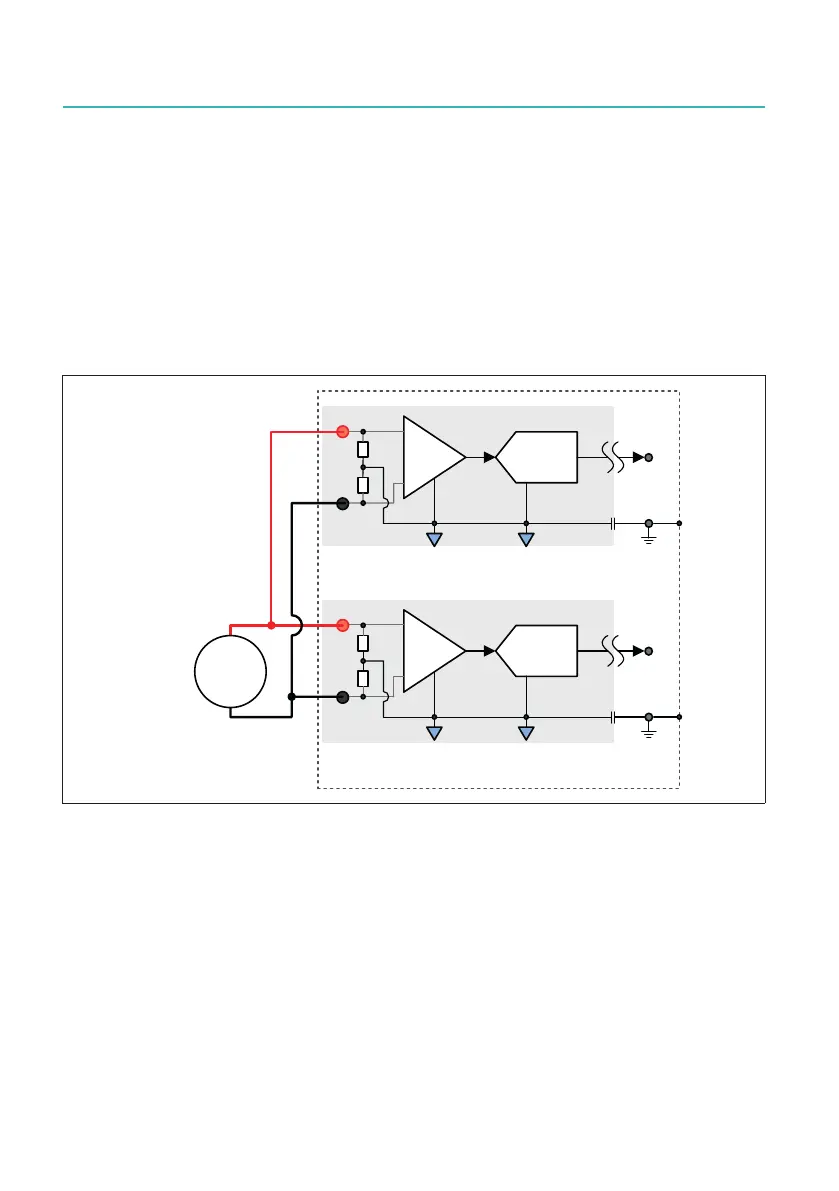
Active input switch test
To guarantee the stability of the channels, the input relays are tested with the maxi-
mum input voltage (1000 V) applied. The inputs of the channels have been switched
from isolated GND to DC by the input relay, resulting in the 1000 V being applied to the
input as a step pulse.
This test is performed with the highest input range (± 1000 V) and repeated with the
lowest input range (± 20 mV). Both tests are performed with an input voltage of 1000 V
and repeated over 1000 times. These tests have all passed successfully.
$'&
,VRODWHGFKDQQHO
$'&
,VRODWHGFKDQQHO
&KDVVLV
9'&
Fig. 12.52 Engineering input switching test
12.3.9 GN610B/GN611B protection mechanisms
Overvoltage and current protection
Allsignalinputsareprotectedagainstvoltageoverload.Thisisspeciedat±1000V
for all ranges, except for the ± 1000 V range that is limited to ± 1250 V. Exceeding these
limits can damage the input card.
GN610B/GN611B input overload protection
The input section has several methods to protect against voltage overload on
the input.

 Loading...