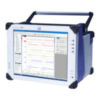
GEN7iB
348
UNDERSTANDING INPUTS AND USAGE OF PROBES
UNDERSTANDING INPUTS AND USAGE OF PROBES
15
Impor
To perform the compensation correctly, both impedances must have the same value,
i.e. R
1
* C
1
= R
2
* C
2
. In practice, R
1
* C
1
will never be equal to R
2
* C
2
, but the values can
be approximated. The probe’s compensation capacitor is usually adjustable somewhere
between 10pF and 50pF to compensate for the instrument’s input capacitance. Since
the Universal Amplier has a 100pF capacitance, the compensation cannot be performed
correctly with standard probes. Therefore, the probe capacitance must be adapted to this
situation.Various probe manufacturers offer the possibility to purchase probes with other
compensation ranges on request.
15.3.3 Probes and differential measurements
Connectingthedifferentialamplierorprobetothesignalsourceisgenerallyamajor
source of error. To maintain the input match, both paths should be as identical as
possible. Any cabling should be the same length for both inputs. If individual probes
are used for each signal line, they should be the same model and have the same cable
length. When measuring low-frequency signals with large common mode voltages,
avoid the use of attenuating probes. At high gains, they simply cannot be used as it
is impossible to balance their attenuation precisely. When attenuation is needed for
high-voltage or high-frequency applications, special passive probes designed specif-
ically for differential applications should be used. These probes have provisions for
precisely trimming the DC attenuation and AC compensation. To get the best perfor-
mance,asetofprobesshouldbededicatedtoeachspecicamplierandcalibrated
withthatamplierusingtheprocedureincludedwiththeprobes.

 Loading...