GEN7iB
198
INPUT CARDS
INPUT CARDS
12
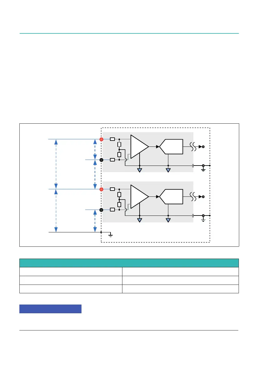
12.2.8 GN310B/GN311B Isolation Voltage channel
AnoverviewoftheGN310B/GN311Bcardisolationandinputisshowninthegures
below.Theisolationwithinavoltagechannelisqualiedas1500VDCand1000VCAT
IVbasic.Theinsulationofthevoltagechanneltochassisisqualiedas1000VCATIII
and 600 V CAT IV reinforced or double. If one voltage channel has its common mode
at +1000 V and one at -1000 V (with respect to chassis), the voltage between the two
channelsis2000V.ThestandardsatwhichthecardiscertiedisIEC61010-1:2010
and IEC61010-2-030:2010.
Voltage Channels Isolation IEC 61010-2-030:2017
$'&
,VRODWHGYROWDJHFKDQQHO
9
&$7,,,
9&$7,9
9
&$7,,,
9&$7,9
9'&&$7,,,
9&$7,9
9
9
$'&
,VRODWHGYROWDJHFKDQQHO
&KDVVLV
Fig. 12.19 Voltage channels isolation ratings
Voltage Channels Isolation
Positive input pin to negative input pin 1500 V DC CAT III, 1000 V CAT IV
Input pin to chassis 1000 V CAT III, 600 V CAT IV
Channel to channel 2000 V RMS
Each of the specications have to be met. The most stringent specication applies in each
situation.

 Loading...