GEN7iB
20
SAFETY MESSAGES
SAFETY MESSAGES
2
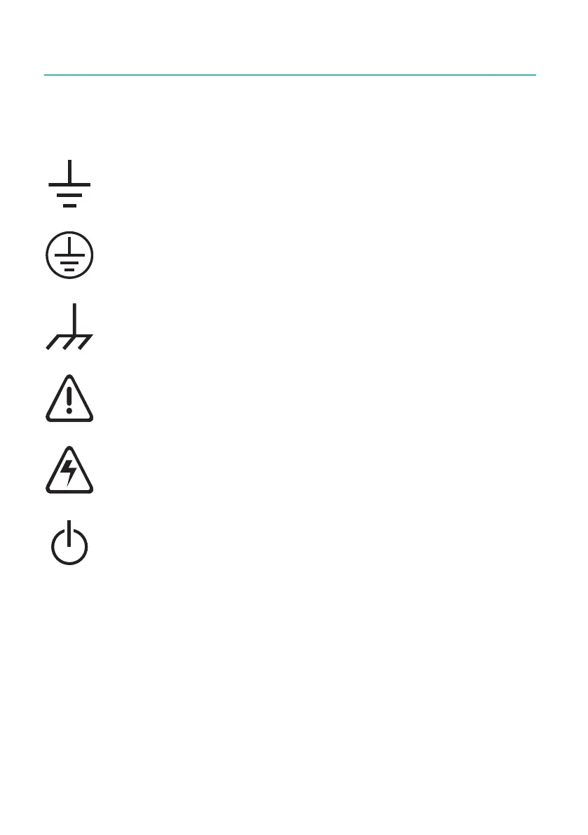
2.3 Instrument Symbols
A variety of symbols can be found in the system. Below is a list of symbols and their
meaning.
This symbol is used to denote the measurement ground connection.
This point is not a protective ground connection.
This symbol is used to denote a protective ground connection.
This symbol is used to denote a frame or chassis ground connection.
This point is not a protective ground connection.
Where caution is required, this symbol refers to the user manual for
further information.
This symbol warns that high voltages are present close to this symbol.
This symbol shows that the switch is a power switch. When pressed,
the instrument state toggles between the operating and power-off
mode. When the system is in power-off mode, all electronics are dis-
connected from the power, except for a small circuit used to detect the
switch state.

 Loading...