GEN7iB
347
UNDERSTANDING INPUTS AND USAGE OF PROBES
UNDERSTANDING INPUTS AND USAGE OF PROBES15
15.3.2 10X Probes
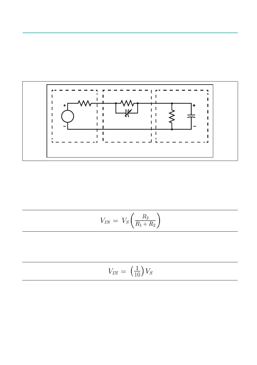
10X probes (also called 10:1 probes, divider probes, or attenuating probes) have a
resistor and capacitor (in parallel) inserted into the probe. Fig. 15.13 shows the circuit
diagram for the 10X probe connected to a high-impedance input of an instrument.
5
VUF
5
5
9
6
9
,1
&
&
&LUFXLWXQGHUWHVW 3UREH
,QSXW
Fig. 15.13 Input connection using a 10X probe
Assuming that R
src
is low compared to R
1
and that R
1
* C
1
= R
2
* C
2
, then the effect of
both capacitors cancel each other out in this circuit. The capacitor is usually adjust-
able and can be tweaked for a nearly perfect match. In these conditions, the relation-
ship of VS to VIN is:
(EQ4)
R
2
istheinputresistanceoftheinstrument'shighinputimpedance(1MΩ)and
R
1
= 9 * R
2
. Using the previous equation, this results in:
(EQ5)
Thenalresultisaprobe/instrumentinputcombinationthathasamuchwider
bandwidth than the 1X probe due to the effective cancellation of the two capacitors.
However, the instrument now measures only one-tenth of the original voltage (hence
the name 10X probe). The circuit being measured is affected with a load impedance of
R
1
+ R
2
=10MΩ,whichismuchhigherthanwiththe1Xprobe.

 Loading...