GEN7iB
97
SETTING UP THE GEN7iB
SETTING UP THE GEN7iB
7
7.7 Digital Event/Timer/Counter
&'
$
%
&
'
(
()
$%
$
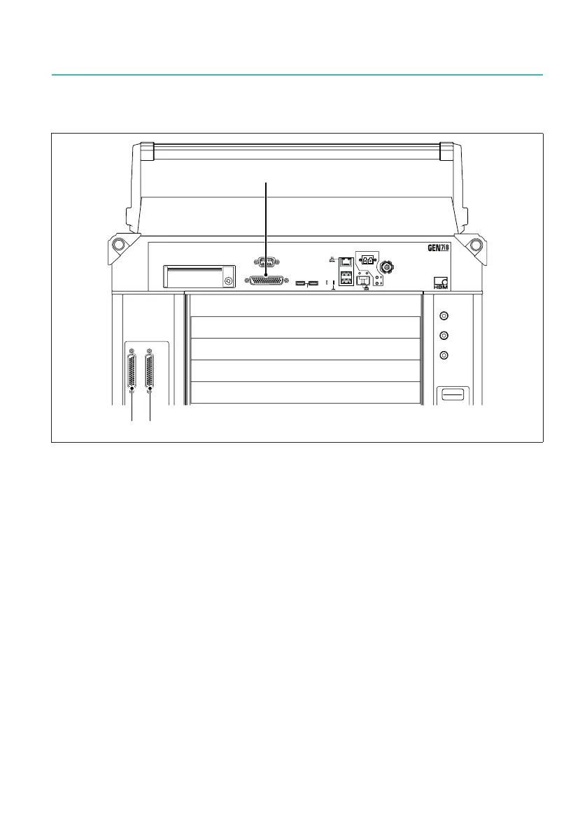
Fig. 7.16 Digital Event/Timer/Counter
A Digital Event/Timer/Counter 1 (AB)
B Digital Event/Timer/Counter 2 (CD)
C Digital Event/Timer/Counter 3 (EF)
The GEN7iB mainframe comes with three Digital Event/Timer/Counter connectors.
These connectors are internally connected to Slots A to F of the mainframe. Each Digi-
tal Event/Timer/Counter connector is wired to one pair of acquisition Slots; Connector
1 to Slots A and B, Connector 2 to Slots C and D and Connector 3 to Slots E and F.
● Acquisition card(s) installed in Slot A and/or B can use the inputs of the Digital
Event/Timer/Counter Connector 1 (AB).
● Acquisition card(s) installed in Slot C and/or D can use the inputs of the Digital
Event/Timer/Counter Connector 2 (CD).
● Acquisition card(s) installed in Slot E and/or F can use the inputs of the Digital
Event/Timer/Counter Connector 3 (EF).

 Loading...