GEN7iB
340
UNDERSTANDING INPUTS AND USAGE OF PROBES
UNDERSTANDING INPUTS AND USAGE OF PROBES
15
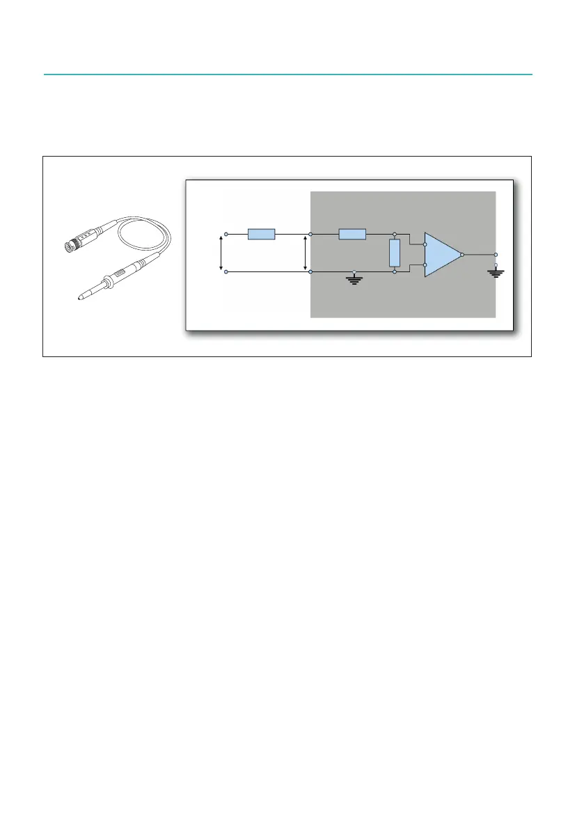
15.2.1 Passive, single-ended voltage probes
Voltageprobesdivideasingle-endedinputsignalbyaspecicfactor.
8
LQ
8
LQ
3DVVLYH3UREH
*1'
*1'
6LQJOHHQGHGDPSOLILHU
0 .
.
Fig. 15.7 Typical example of a voltage probe
Theoretically, voltage probes are simply passive in-line resistors in series with the
positiveinputofasingle-endedamplier.Togetherwiththeinputresistoroftheampli-
er,theyformavoltagedividersothatthevoltageinserieswiththeamplieritselfis
divided. As there is also a capacitive component in this divider, the input capacitance
oftheamplierandtheso-called“compensationrange”oftheprobeneedtomatch.
Otherwise, signal distortion might occur.
By selecting a higher resistance probe, the divider ratio increases so that large input
ranges can be achieved. Voltage probes do not provide or add either isolation or
common mode voltage rejection. These probes can only be used in series with sin-
gle-endedampliers.
Voltage probes typically decrease the overall accuracy of the system (caused by the
inaccuracy of the input divider ratio formed by the external probe resistance and the
internalamplierresistance).

 Loading...