GEN7iB
249
INPUT CARDS
INPUT CARDS
12
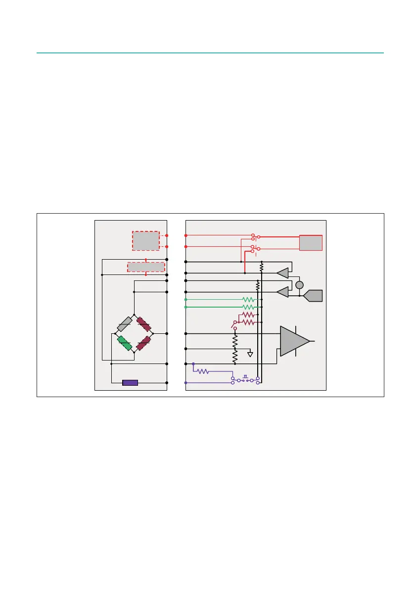
12.6.3 Bridge mode and cabling
Bridgeamplierconguration
Input diagrams and typical connection diagrams for the GN840B/GN1640B bridge
mode are shown on this and the following pages. For the maximum versatility, the
ampliersallowawiderangeofcongurations.Aminimumofthreewiresareneces-
sary for a quarter- or half-bridge sensor and four wires for a full bridge. Optional remote
sensing of excitation voltage is supported for precision transducer applications, which
adds two wires. If remote sense is not required, the sense wires must be connected
within the channel connector as the sense lines are always active. Remote shunt cali-
bration is possible with the addition of one more wire. An isolated common is provided
for preferred double shielding.
7('6&ODVV
7('6
&ODVV
RSWLRQDO
%ULGJHVHQVRU
6KXQW
5
5
5
5
$PSOLILHU
([FLWDWLRQ
6HQVH
([FLWDWLRQ
6HQVH
([FLWDWLRQ
óEULGJH
6LJQDO
6LJQDO
òEULGJH
6LJQDOJURXQG
7('6
&RQWURO
7HGV
7HGV
9
9
7('6FODVV
([WHUQDOVKXQW
&$/
6LJQDOFRQGLWLRQHU
8
H[FLW
,QWVKXQW
0
0
óEULGJH
3RVQHJ
,QWH[W
Fig. 12.64 Bridge mode block diagram
Bridge completion
Eachbridgeamplierchannelcontainsapairofxed10kΩresistorsforhalfbridge
completion that can be switched in by software control. Additional pins on the input
connectorprovideaprecision120Ωand350Ωresistorforquarter-bridgecompletion.

 Loading...