GEN7iB
271
INPUT CARDS
INPUT CARDS
12
5(6(59('
5(6(59('
5(6(59('
5(6(59('
5(6(59('
5(6(59('
5(6(59('
5(6(59('
5(6(59('
6,**5281'
6,**5281'
6,**5281'
9RXWSXW
9RXWSXW
9RXWSXW
5(6(59('
5(6(59('
&+1(*
&+326
&+1(*
&+326
&+1(*
&+326
&+1(*
&+326
&+1(*
&+326
&+1(*
&+326
&+1(*
&+326
&+1(*
&+326
5(6(59('
&+1(*
&+326
&+1(*
&+326
&+1(*
&+326
&+1(*
&+326
&+1(*
&+326
&+1(*
&+326
&+1(*
&+326
&+1(*
&+326
5(6(59('
5(6(59('
5(6(59('
5(6(59('
5(6(59('
5(6(59('
5(6(59('
5(6(59('
5(6(59('
6,**5281'
6,**5281'
6,**5281'
9RXWSXW
9RXWSXW
9RXWSXW
5(6(59('
5(6(59('
&+1(*
&+326
&+1(*
&+326
&+1(*
&+326
&+1(*
&+326
&+1(*
&+326
&+1(*
&+326
&+1(*
&+326
&+1(*
&+326
5(6(59('
&+1(*
&+326
&+1(*
&+326
&+1(*
&+326
&+1(*
&+326
&+1(*
&+326
&+1(*
&+326
&+1(*
&+326
&+1(*
&+326
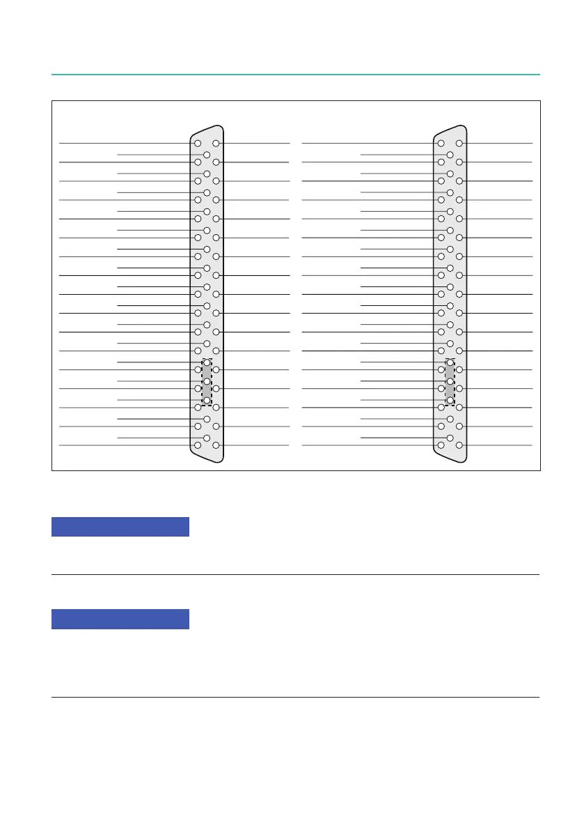
Fig. 12.88 Pin diagram for top 16 channel connector (left), Bottom 16 channel connector (right)
Both positive and negative pins must be connected to avoid erroneous measurement
results with noise.
There are three output pins available on each connector. Each pin's output voltage is 5V.
The maximum current for each pins is 0.1 A. When connecting all three pins 0.3 A can be
used.
Over current protection is add for the maximum 0.3 A using an automatic resettable fuse.
For more information on the 16/32 Channel Basic Card 20 kS/s input card, please refer
to the GN3211 data sheet.

 Loading...