121
_____________________________________________________________________________________________
8.1 External I/O Terminal
______________________________________________________________________________________________
H.V.ON
―――――――
READY
―――――――
TEST
――――――
Voltage Output
W-MODE
――――――――――
I-MODE
―――――――――
140 ms max.
H.V.ON
―――――――
READY
―――――――
TEST
――――――
Voltage Output
W-MODE
――――――――――
I-MODE
―――――――――
100 ms max.
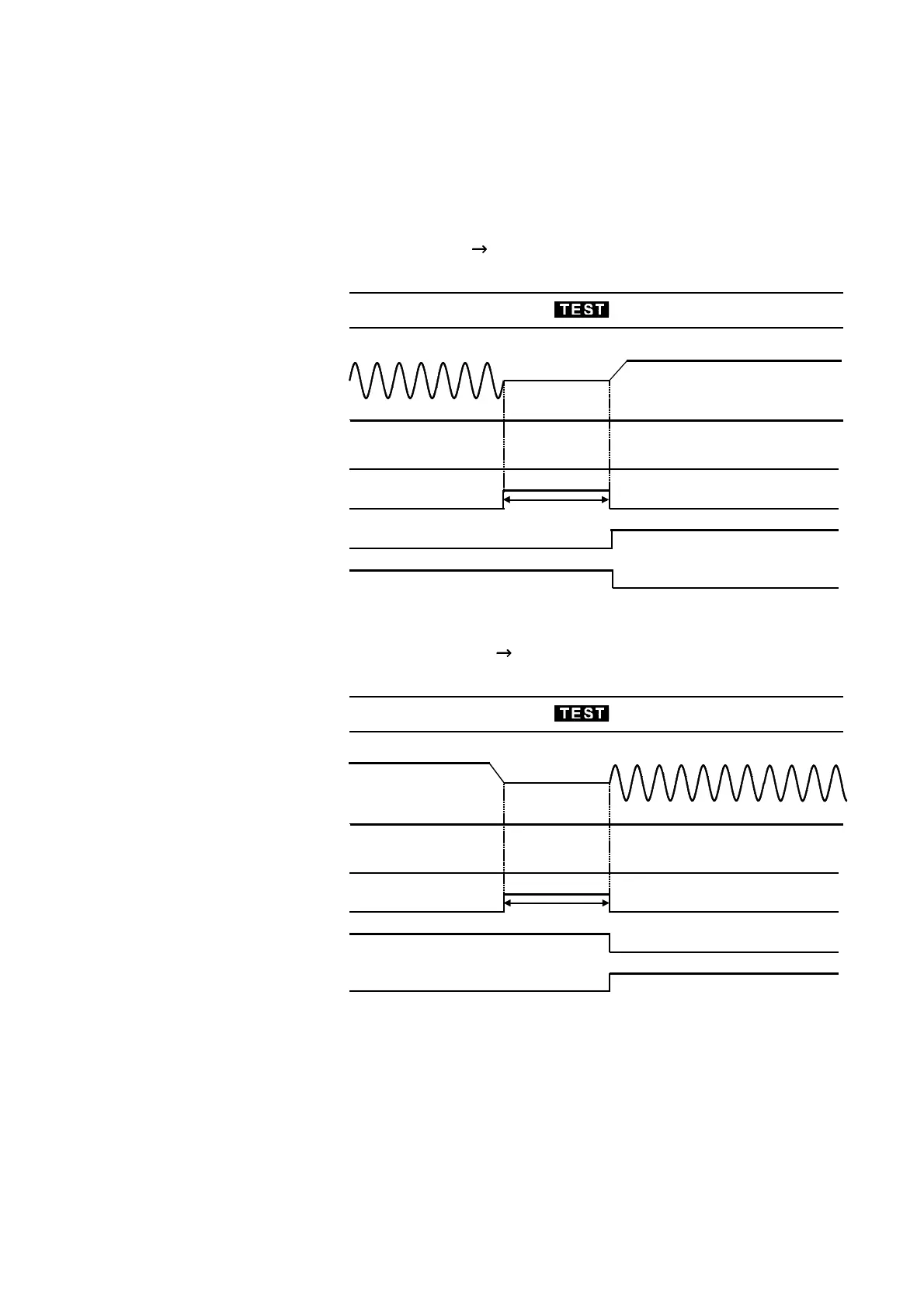
(4) Auto test mode switching Timing chart
This figure shows the timing chart of the unit when it is switched to Auto
test mode which conducts voltage and insulation resistance tests
successively. The unit does not switch to the next test until the measured
voltage value drops sufficiently. The TEST signal remains LOW level until
the series of tests is complete.
Withstand-voltage test
Insulation-resistance test
Insulation-resistance test Withstand-voltage test