41
_____________________________________________________________________________________________
3.5 PASS or FAIL Determination
______________________________________________________________________________________________
NOTE
If the current generated is several times as large as the upper-limit value, a circuit
promptly cuts off the high voltage, thereby switching the unit to
UPPER FAIL
.At
this point, an incorrect value for the measured current is displayed.
If the optional "Voltage Comparator Position" function is set to "
1
:Endoftest
time", since the unit shifts to the TEST state whenever voltage is output,
TEST
does not flash before the output-voltage value reaches the comparative-voltage
value ran
e.
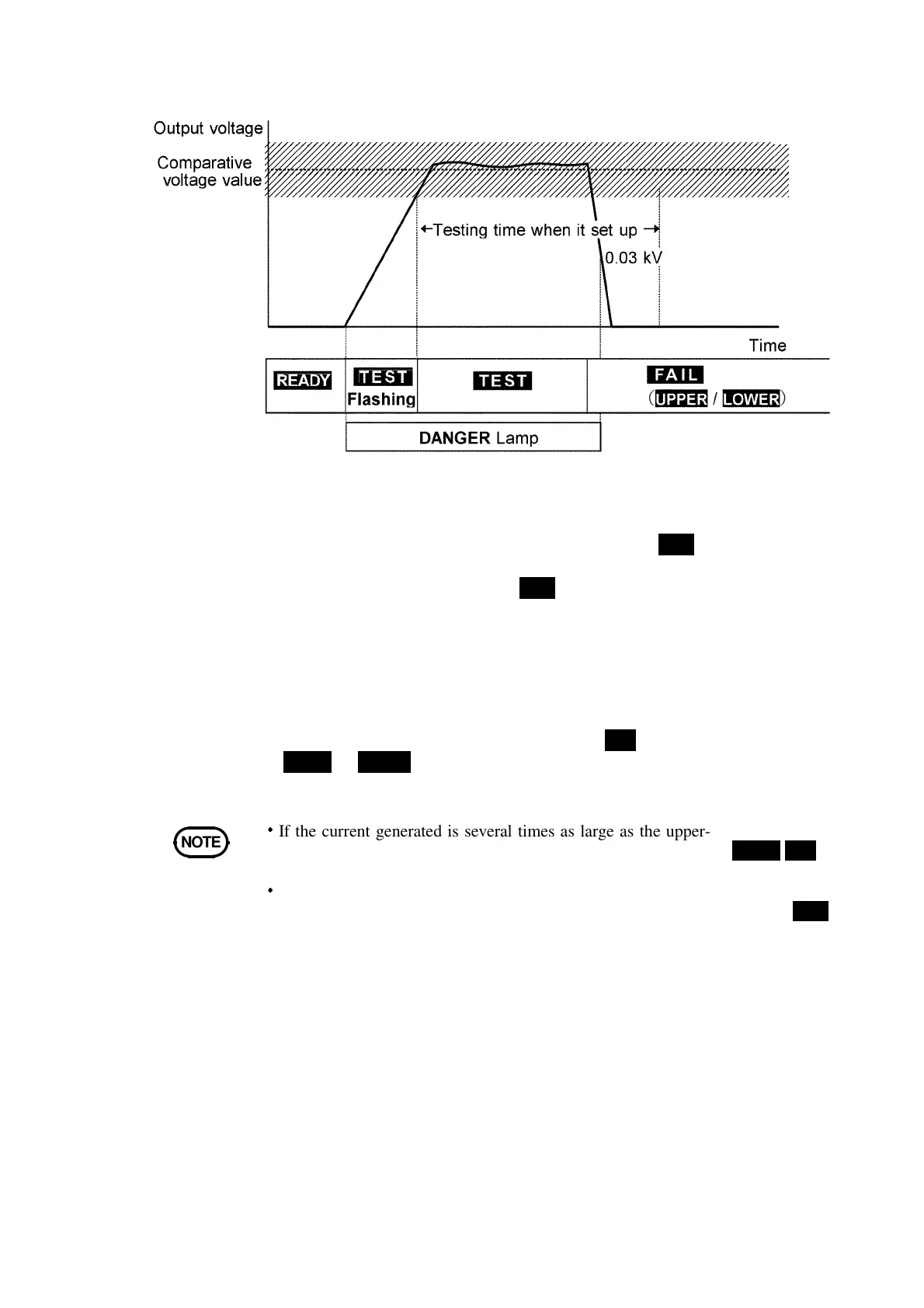
Flow of FAIL determination
1.
Press the START key to start a test.
2.
When a comparative-voltage value has been set,
TEST
flickers until the
output voltage switches to the comparative-voltage range. Once the output
voltage switches to this range,
TEST
lights up and the reduction timer
begins counting down the test time.
3. A voltage continues to be output until the test time elapses. If the
measured current deviates from the upper- or lower-level value during this
period, the unit switches to the FAIL state.
4.
Once a switch is made to the FAIL state,
FAIL
lights up, together with
UPPER
or
LOWER
. The unit stops outputting a voltage and the reduction
timer stops.