4−36
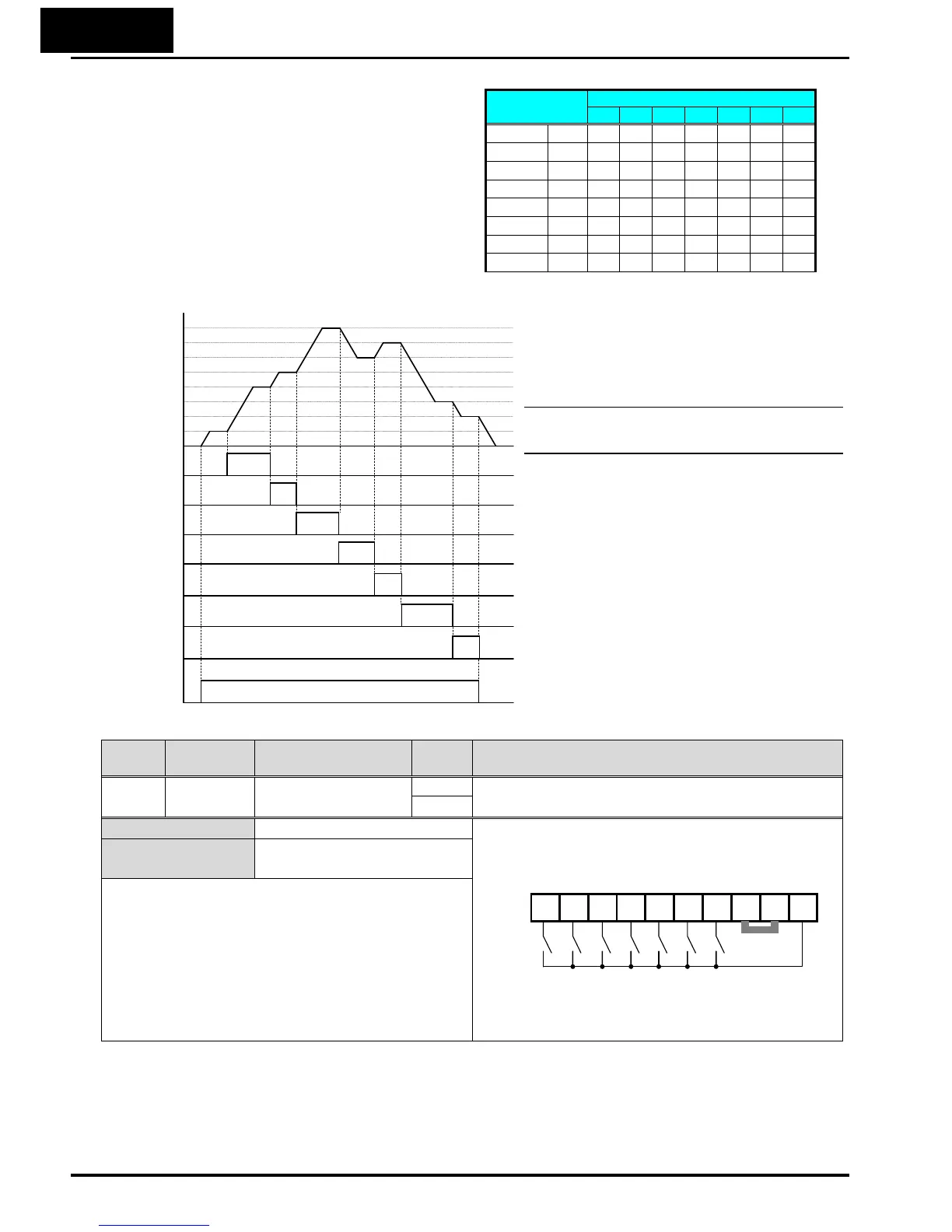
The inverter can store up to 16
different target frequencies (speeds)
that the motor output uses for
steady-state run condition. These
speeds are accessible through
programming seven of the intelligent
terminals as bit-encoded inputs SF1 to
SF7 per the table to the right. These
can be any of the six inputs, and in
any order. You can use fewer inputs if
you need eight or fewer speeds.
The example with eight speeds in the
figure below shows how input switches
configured for SF1–SF7 functions can
change the motor speed in real time.
NOTE: Speed 0 depends on A001
parameter value.
Option
Code
Terminal
Symbol
Function Name State Description
32~
38
SF1~SF7 Multistage Speed
~Bit Operation
ON Makes multistage speed by combination of the
inputs.
OFF
Valid for inputs:
C001~C007
Example (default input configuration shown—see
page 3–84):
See I/O specs on page 4–6.
Required settings
F001, A001=02,
A020 to A035
Notes:
• When programming the multi-speed settings, be
sure to press the SET key each time and then set
the next multi-speed setting. Note that when the
key is not pressed, no data will be set.
• When a multi-speed setting more than 50Hz
(60Hz) is to be set, it is necessary to program the
maximum frequency A004 high enough to allow
that speed
Multi-
speed
Input Function
SF7 SF6 SF5 SF4 SF3 SF2 SF1
Speed 0
A020
0 0 0 0 0 0 0
Speed 1
A021
X X X X X X
1
Speed 2
A022
X X X X X
1
0
Speed 3
A023
X X X X
1
0
0
Speed 4
A024
X X X
1
0
0 0
Speed 5
A025
X X
1
0
0 0 0
Speed 6
A026
X
1
0 0
0 0 0
Speed 7
A027
1
0 0 0
0 0 0
Speed
0th
4th
6th
1st
2nd
5th
7th
3rd
1
0
1
0
1
0
1
0
[SF1]
[SF2]
[SF3]
[SF4]
1
0
[SF5]
1
0
[SF6]
1
0
[SF7]
1
0
[FW]
SF7 SF6 SF5 SF4 SF3 SF2 SF1
7654321LPCSP24
PLC

 Loading...


