4−62
Undervoltage Signal
The inverter outputs the undervoltage signal when it detects that the inverter is in
undervoltage situation.
To enable this function, assign “09 (UV)” to an intelligent output terminal.
Option
Code
Terminal
Symbol
Function Name State Description
09
UV Undervoltage signal ON Inverter is in undervoltage
OFF Inverter is in normal condition
alid for inputs:
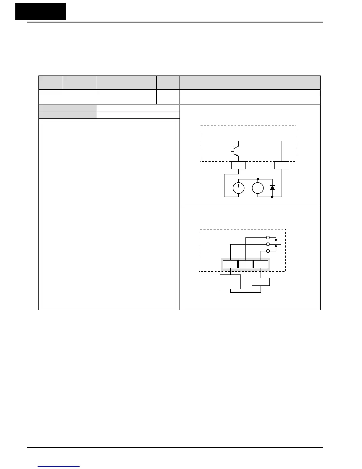
11, 12, AL0 – AL2 Example for terminal [11] (default output
configuration shown – see page 3-90):
Example for terminal [AL0], [AL1], [AL2] (requires
output configuration – see page 4-52 and 3-90):
See I/O specs on page 4-6
Required settings
Notes:
• The example circuit for terminal [11] drives a relay
coil. Note the use of a diode to prevent the
negative-going turn-off spike generated by the coil
from damaging the inverter’s output transistor.
RY
Inverter output
terminal circuit
CM2 11
UV
AL1
Power
supply
Load
AL0 AL2
Inverter logic
circuit board
UV

 Loading...


