99 Ensure the pulses are positioned according to the setup time of the setup/hold
combination selected, +0.0 ps or − 100 ps.
aa In the oscilloscope Delta V menu, set the Marker 1 Position to Chan 1, then set
Marker 1 at − 1.3000 V. Set the Marker 2 Position to Chan 2, then set Marker 2 at
− 1.3000 V.
bb In the oscilloscope Delta T menu, select Start on Neg Edge 1. Select Stop on Neg
Edge 1.
cc If necessary, adjust the pulse generator channel 2 Delay, then select Precision Edge
Find in the oscilloscope Delta T menu. Repeat this step until the pulses are aligned
according to the setup time of the setup/hold combination selected, +0.0 ps or
− 100 ps.
1010
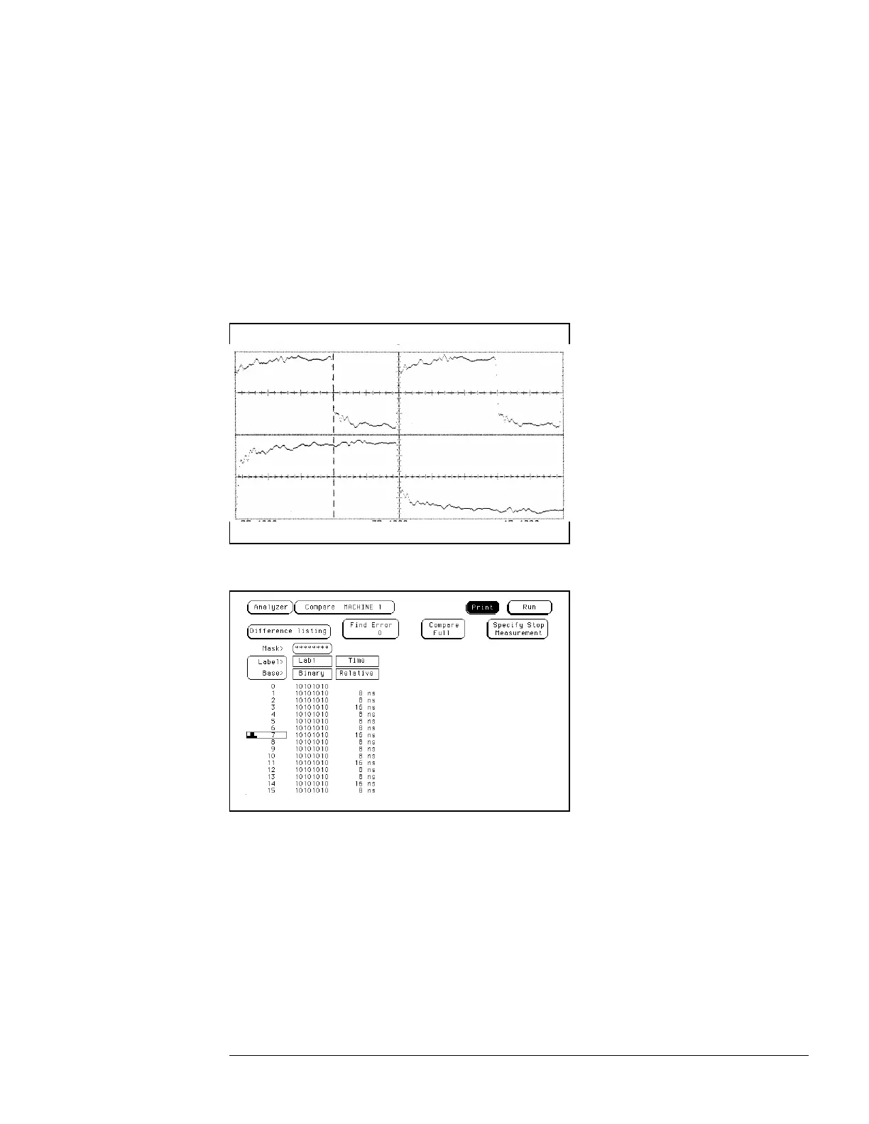
Repeat steps 4, 5, 6, and 7. The Compare file for this portion of the procedure will
consist of all 10101010. Begin with the first clock listed in step 4.
1111 Test the next setup/hold combination.
aa In the logic analyzer Format menu, select Master Clock.
bb Turn off and disconnect the clock just tested.
cc Repeat steps 1 through 10 for the next setup/hold combination listed in step 1 on
page 3–54, until all listed setup/hold combinations have been tested.
When aligning the data and clock waveforms using the oscilloscope, align the waveforms
according to the setup time of the setup/hold combination being tested, +0.0 ps or − 100 ps.
To test the single-clock, multiple-edge, state acquisition (logic analyzer)
3–57

 Loading...


