330
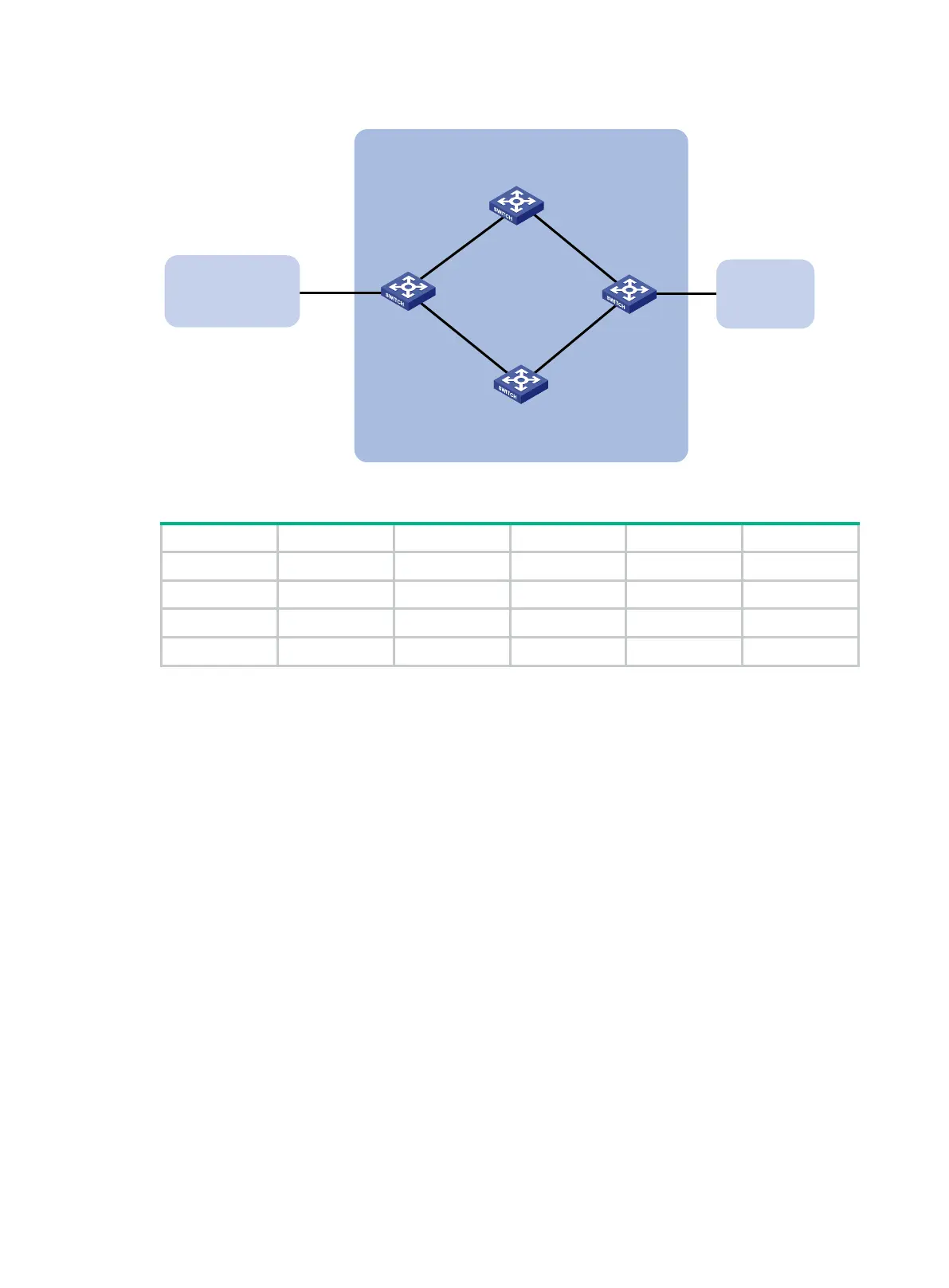
Figure 75 Network diagram
Table 19 Interface and IP address assignment
Switch A Vlan-int100 3.0.1.1/24 Switch C Vlan-int101 3.0.2.2/24
Vlan-int200 2.0.1.1/24 Vlan-int201 2.0.2.2/24
Switch B Vlan-int100 3.0.1.2/24 Switch D Vlan-int200 2.0.1.2/24
Vlan-int101 3.0.2.1/24 Vlan-int201 2.0.2.1/24
Configuration procedure
1. Configure IP addresses for interfaces. (Details not shown.)
2. Configure OSPF to ensure that Switch A and Switch C are reachable to each other. (Details not
shown.)
3. Configure BGP on Switch A:
# Establish two IBGP connections to Switch C.
<SwitchA> system-view
[SwitchA] bgp 200
[SwitchA-bgp-default] peer 3.0.2.2 as-number 200
[SwitchA-bgp-default] peer 2.0.2.2 as-number 200
[SwitchA-bgp-default] address-family ipv4 unicast
[SwitchA-bgp-default-ipv4] peer 3.0.2.2 enable
[SwitchA-bgp-default-ipv4] peer 2.0.2.2 enable
[SwitchA-bgp-default-ipv4] quit
[SwitchA-bgp-default] quit
# Create IPv4 basic ACL 2000 to permit 1.1.1.0/24 to pass.
[SwitchA] acl basic 2000
[SwitchA-acl-ipv4-basic-2000] rule permit source 1.1.1.0 0.0.0.255
[SwitchA-acl-ipv4-basic-2000] quit
# Create two routing policies to set the MED for route 1.1.1.0/24. The policy apply_med_50
sets the MED to 50, and the policy apply_med_100 sets the MED to 100.
[SwitchA] route-policy apply_med_50 permit node 10
Switch A Switch C
AS 200
Switch D
Vlan-int200
Vlan-int201
Switch B
AS 300
Vlan-int101Vlan-int100
Vlan-int100
Vlan-int101
Vlan-int200
Vlan-int201
AS 100
1.1.1.0/24

 Loading...


