O.12 Part. N. 8000 H1344 (10-2009)
“KIT” ASSEMBLING INSTRUCTIONS
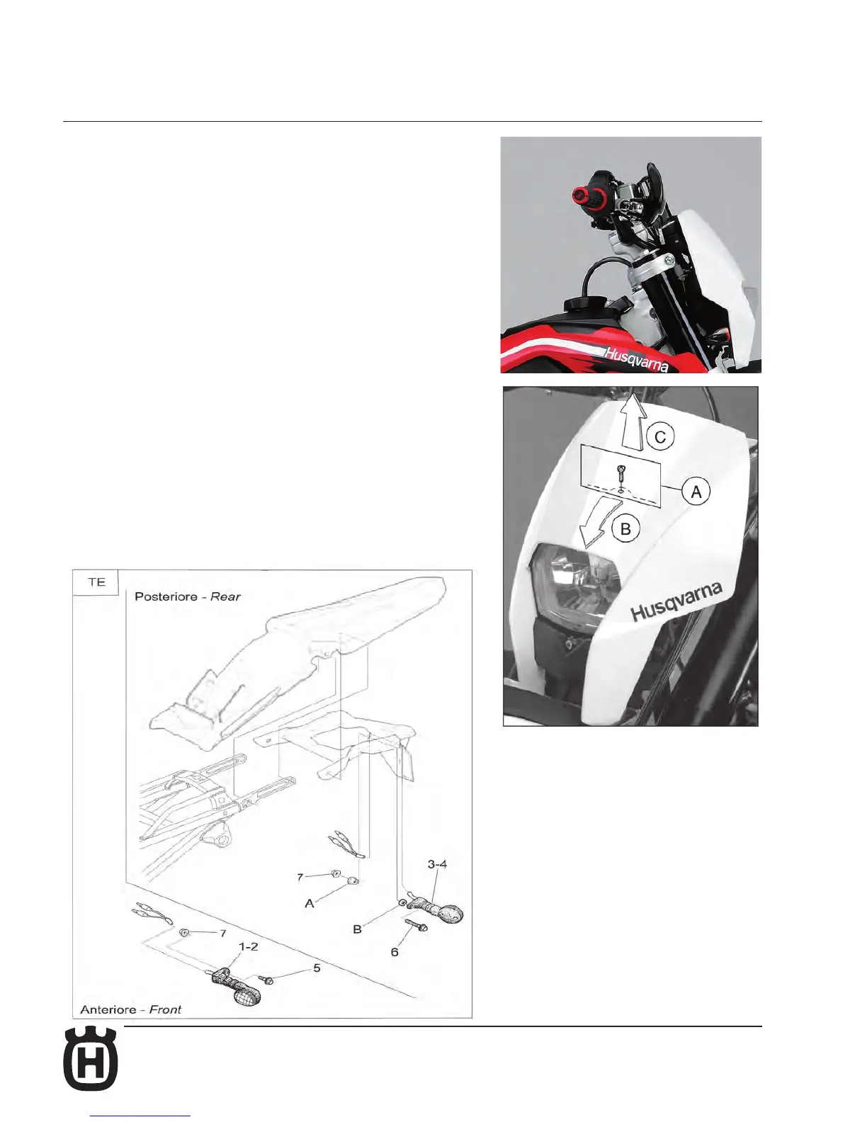
6- Turn signals KIT (TE)
FRONT TURN SIGNALS
Remove the upper fastening screw of the the headlamp carrier to the instrument
panuel support (A);
- push forward the headlamp carrier (B) and pull it towards the high (C) in order
to uncouple from the two lower supports.
- remove the headlamp carrier and x over it the blinkers using the nuts (3).
Reassemble the headlamp carrier with the assembled blinkers linking the
blinkers to the mail cable harness (follow the electrical schema at page O. 15).
1- L.H. front turn signal (no. 1 piece)
2- R.H. front turn signal (no. 1 piece)
3- L.H. rear turn signal (no. 1 piece)
4- R.H. rear turn signal (no. 1 piece)
5- Screw M6x16 mm (no. 2 pieces)
6- Screw M6x40 mm (no. 2 pieces)
7- Nut M6 (no. 4 pieces)
8- Turn signal asher (no.1 piece)
11- Flasher support bracket (no. 1 piece)