M.25Part. N. 8000 H1344 (10-2009)
ELECTRIC SYSTEM, DIGITAL INSTRUMENT
1
3
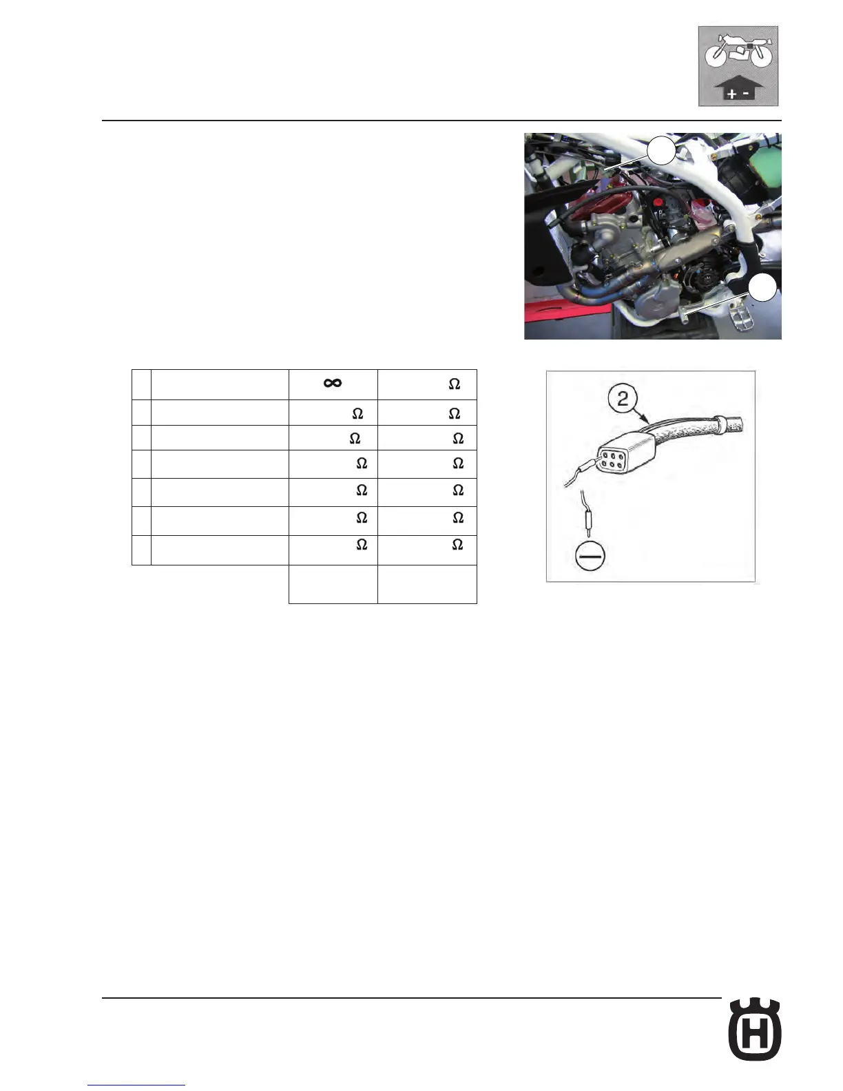
Gear shift position sensor checking (GPS: Gear Position Sensor)
Set the tester on "Ohm" position then detach the 6 ways connector (1) from the
main wiring harness (the gear shift position sensor is fastened on the alterna-
tor cable with a clamp). Ground a tester terminal on the engine then insert the
other one in the hole where is the gear sensor BLACK cable (2). The lever (3) is
placed on the left-hand side of the engine. After every shift, the lever automati-
cally returns to horizontal position. First gear is engaged by pushing the lever
downwards; all the other gears are engaged, by pushing the lever upwards. See
the table below for the data to be checked.
A NEUTRAL (open circuit) 312÷319
B 1st gear 556÷568 725÷739
C 2nd gear 817÷833 1,31÷1,34 K
D 3rd gear 1,48÷1,51 K 2,18÷2,23 K
E 4th gear 2,71÷2,77 K 3,61÷3,68 K
F 5th gear 6,75÷6,88 K 6,58÷6,71 K
G 6th gear 14,8÷15,1 K 15,2÷15,5 K
TC-TXC
TE-SMR