Z.5Part. N. 8000 H1344 (10-2009)
NOTES FOR USA/CDN- AUS MODELS
- SMR
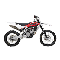
C: First turn counterclockwise fastening rear pin (1) then remove
saddle, loosen the screws (2) with a 8 mm T-shaped spanner and
remove the L.H. side panel (3) (do the same on the right side). Using
an 8 mm T-shaped spanner on the outside and a 10 mm T-shaped
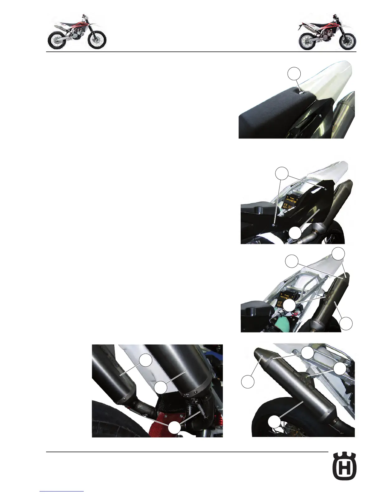
spanner on the inside, remove the locking screw (4) of the mufer
(A) or (B).
D: Remove the spring (5) and pull out the mufer (A) or (B).
Note*: If silencer or exhaust are difcult to remove, help to slide
them apart by tapping gently with a rubber or plastic hammer.
C: remove the four rivets (6), clamp and the endcap (7) from si-
lencer’s body;
D: examinate SPARK ARRESTER conditions and remove, if neces-
sary, carbon particles from the SPARK ARRESTER screen;
E: if necessary, inate air on the SPARK ARRESTER screen, in the
opposite direction in respect of the exhausted gas ow;
F: assemble the front endcap on the silencer’s body, mounting the
screws in the correct position, providing a tight connection between
endcap and silencer’s body, using, if necessary, a silicone
paste;
G: re-assemble the silencer on motorbike, then L. H. side panel
and saddle.
Due to the SPARK ARRESTER position on the silencer, if you need
only to check the SPARK ARRESTER conditions you can:
A: disassemble the silencer from motorbike;
B: check SPARK ARRESTER conditions simply looking into the
silencer
from front endcap opening;
C: if the check is positive, you can proceed in re-assembling
the silencer on the motorbike;
D: if the check is negative, proceed with the maintenance and
cleanout procedure.
6
7
4
3
2
A
7
4
A
6
5
B
A
1