3. Wiring
3.2 Pulse Train Control Mode
3-31
ME0342-4B
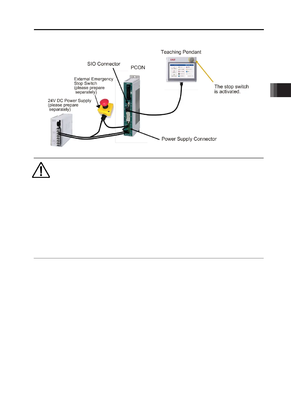
2) Have the emergency stop switch in the equipment and stop switch on the teaching pendant
enabled and have the actuator operated
● Example of Circuit
The emergency stop gets released when +24V is supplied to EMG- Terminal on the controller,
and emergency stop activates if the power supply is shut, and stops the actuator operation,
turns the servo OFF and cuts off the motor power supply inside the controller.
Have an external stop switch connected, and connect +24V to EMG- Terminal via the
emergency stop switch ON the teaching pendant.
+24V supply to EMG- terminal should get shut off when an external emergency stop switch or
an stop switch on the teaching pendant is turned ON, and the condition should get into the
emergency stop status.
3.2 Pulse Train Control Mode
ME0342-4B 3-32
● Image of Wiring
Caution
● When supplying the power by turning ON/OFF the 24V DC, keep the 0V being
connected and have the +24V supplied/disconnected (cut one side only). Shutting
power supply on the both ends may make the electric potential unstable when the
power gets cut on the 0V end first. This may cause malfunction of components inside
the controller.
● The rating for the emergency stop signal (EMG-) is 24V DC and 10mA or less.
● Leave for 1s or more after shutting the power off before rebooting.
● Do not attempt to supply only the motor power without supplying the control power.
● There could be a case that the voltage supplied to the controller drops due to cable
diameter or length, which may generate an alarm. In this case, it is necessary to adjust
the output voltage on the power so the voltage supplied to the controller gets to 24V.

 Loading...


