4. Operation
4.1 Basic Operation
4-6
ME0342-4B
Operation・・・・Example for Parameters (PIO Patterns 0) at Delivery
• Procedure 1 : Input the position number at which positioning is desired to be performed in the
binary data (PC1 to PC32) from a tool such as the host controller, and then turn
the start signal (CSTR) ON.
• Procedure 2 : The actuator is placed at the proper coordinate value (destination) according to
the positioning information in the specified position number.
• Procedure 3 : If the positioning is completed, the binary data (PM1 to PM32) of the position
number is output. The completion signal (PEND) is also output.
The above procedure describes the basic operation method in the “Positioner mode”.
4.1 Basic Operation
ME0342-4B 4-7
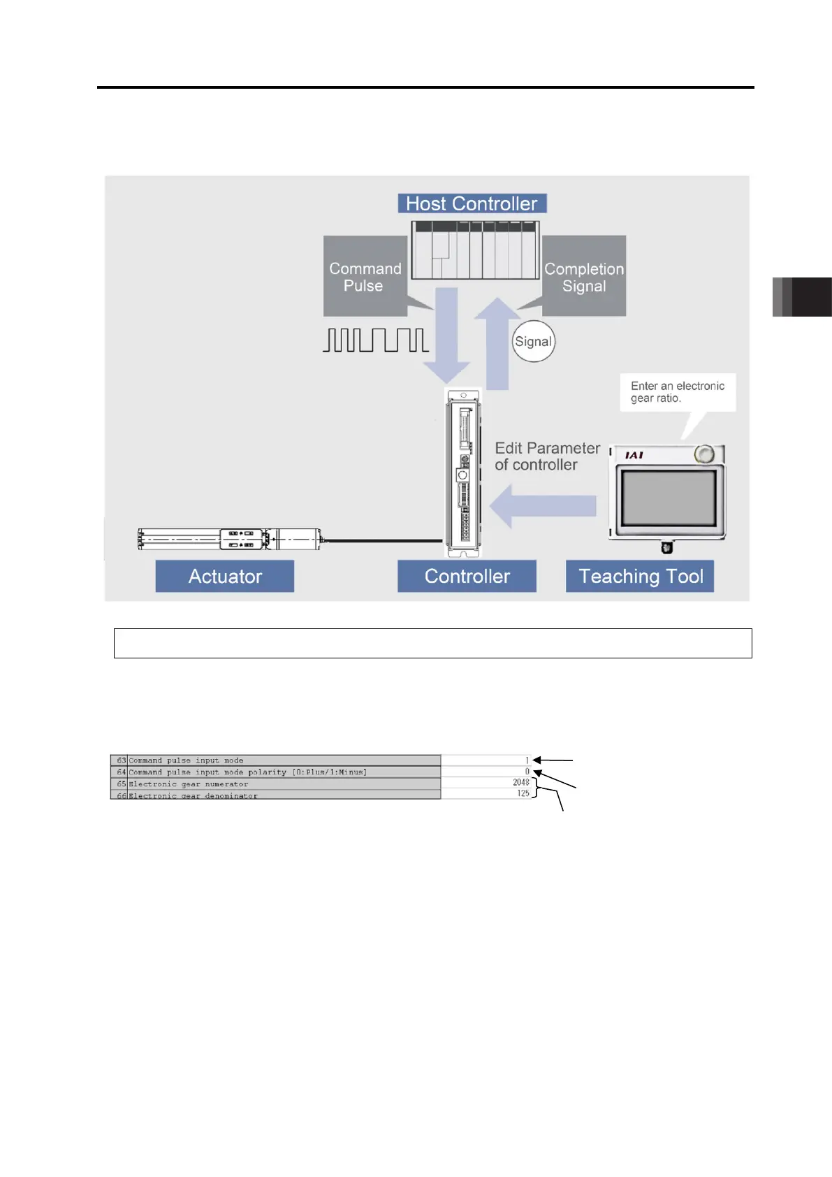
[2] Pulse Train Control Mode
Operation・・・・
Example for When the Parameter Settings at Delivery
• Procedure 1 : Establish the settings for the pulse train form and electronic gear ratio
(to determine how many millimeters the actuator moves when 1 pulse is given)
to the controller parameters by using a teaching tool such as PC Software.
• Procedure 2 : Send the pulse corresponding to the movement amount of the actuator to the
controller from a tool such as the host controller (positioning unit).
• Procedure 3 : The controller calculates the movement amount by multiplying the electronic
gear ratio to the number of the pulse input to the controller. Operation made in
the movement amount from the current position.
The speed fluctuates in response to the speed of the pulse (frequency) to be input.
• Procedure 4 : Once the positioning is complete, the completion signal (INP) is output.
The above procedure describes the basic operation method in the “Pulse train control mode”.
Electronic Gear Ratio = 2048/125 ≒ 16.4 times
(Operation made in Unit movement amount per pulse × 16.4)
Movement direction indication
mode by signal
-Logic Pulse Input

 Loading...


