4. Operation
4.2 Operation in Positioner Mode
4-22
ME0342-4B
4.2.4 Operation Ready and Auxiliary Signals (Common to Patterns 0 to 7)
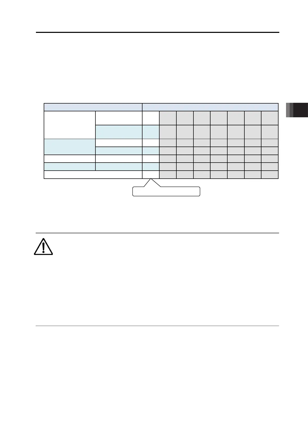
[1] Emergency Stop Status (EMGS)
PIO signal
Common to
Patterns 0 to 7
: Available, ×: Unavailable
1) The emergency stop status EMGS is turned ON when in normal condition and turned OFF
when EMG terminal on [3.1.3 [1] PIO Patterns in Positioner Mode] is 0V (emergency stop
condition or disconnected).
2) It turns back ON once the emergency stop condition is released and EMG terminal goes up
to 24V DC.
Have an appropriate safety treatment such as interlock with this signal for the host controller
(PLC, etc.).
Caution : Caution on First-Order Lag Filter
● It is not an emergency stop output due to an alarm generation of the controller.
[2] Operation Mode (RMOD, RMDS)
PIO signal
Common to
Patterns 0 to 7
: Available, ×: Unavailable
P Two operation modes are provided so that the operation by PIO signals does not overlap with
the operation by a teaching tool such as PC software through SIO communication.
The mode change is normally done by the operation mode setting switch ON the front panel of
the controller.
AUTO ・・・・Operation by PIO signals is valid.
MANU ・・・・Operation through SIO communication is valid.
However, when having the controller in link connection
(Note 1)
and the teaching tool such as
PC software being connected using SIO converter, there is a case the controller and the teaching
tool are placed far from each other. In such a case, the controller can be switched to the “MANU”
mode by setting PIO signal RMOD on.
Because the RMDS signal is set to ON with the “MANU” mode selected by using the signal,
make the operation sequence interlocked.
4.2 Operation in Positioner Mode
ME0342-4B 4-23
The table below lists the switches ON the front panel, the modes selected by the RMOD signal
and the corresponding output states of the RMDS signal.
Note 1 For the details of the link connection, refer to
[9.1 Way to Set Multiple Controllers with 1 Teaching Tool].
: Selected or set to ON, ×: Unselected or set to OFF
Teaching tool such
as PC software
(Note 2)
× × × ×
(Note 2)
× × × ×
Switches ON
front panel
PIO valid: , PIO invalid:
Note 2 "PIO Operation Allowed" and "PIO Operation Invalid" is the function to select a
restriction while the teaching tool such as PC software is connected.
Caution
● Note that selecting “PIO Operation Allowed” by using the teaching tool such as
PC software makes all PIO signals valid to enable operation however the states of the
switches and RMOD signal input may be.
In this status, the actuator may be started depending on the signals from PLC.
● If the teaching tool such as PC software is disconnected from the controller,
“PIO Operation Allowed” or “PIO Operation Invalid” holds the state selected before.
After teaching operation or debugging is terminated, select “PIO Operation Allowed” and
disconnect the teaching tool such as PC software from the controller.

 Loading...


