4. Operation
4.3 Pulse Train Control Mode
4-104
ME0342-4B
4.3.2 Operation Ready and Auxiliary Signals
[1] System Ready (PWR)
PIO signal
The signal is turned ON if the controller can be controlled after main power-on.
It is turned ON once the initialization terminates normally after main power-on and PCON can
be controlled regardless of alarm and servo status.
Even in the alarm condition, when the PCON can control the system, it is turned “ON”.
[2] Emergency Stop Status (EMGS)
PIO signal
1) The emergency stop status EMGS is turned on when in a non-emergency-stop state and
turned off when EMG terminal on [3.1.3 [1] Power Supply Connector (for Power Supply and
Emergency Stop)] is 0V (emergency stop condition or disconnected).
2) It turns back ON once the emergency stop condition is released and EMG terminal goes up
to 24V DC. Have an appropriate safety treatment such as interlock with this signal for the
host controller (PLC, etc.).
Caution
● It is not an emergency stop output due to an alarm generation of the controller.
[3] Operation Mode (RMOD, RMDS)
PIO signal
Two operation modes are provided so that the operation by PIO signals does not overlap with
the operation by a teaching tool such as PC software through SIO communication.
The mode change is done by the operation mode setting switch on the front panel of the
controller.
AUTO ········Operation by PIO signals is valid.
MANU ········Operation through SIO communication is valid.
4.3 Pulse Train Control Mode
ME0342-4B 4-105
However, the controller is subject to link connection
(Note 1)
to connect with a teaching tool such as
the PC dedicated teaching software by using a SIO converter, the controller may be far apart from
the teaching tool.
In such a case, the controller can be entered into the "MANU" mode by setting PIO signal RMOD
to ON.
Because the RMDS signal is set to ON with the "MANU" mode selected by using the signal,
make the operation sequence interlocked.
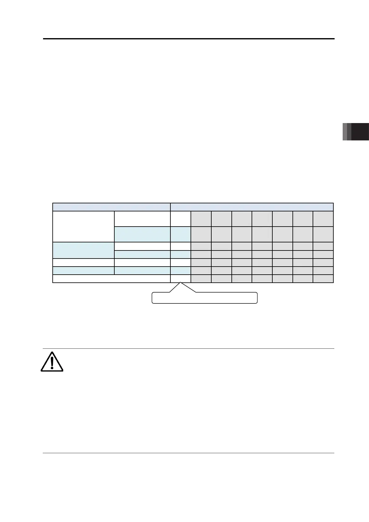
The table below lists the switches on the front panel, the modes selected by the RMOD signal
and the corresponding output states of the RMDS signal.
Note 1 For the details of the link connection, refer to [9.1 Way to Set Multiple Controllers
with 1 Teaching Tool].
: Selected or set to ON ×: Unselected or set to OFF
Teaching tool such
as PC software
(Note 2)
× × × ×
(Note 2)
× × × ×
PIO valid: , PIO invalid:
Note 2 "PIO valid" and "PIO invalid" is the function to select a restriction while the teaching
tool such as PC software is connected.
Caution
● Note that selecting “PIO start enable” by using the teaching tool such as PC software
makes all PIO signals valid to enable operation however the states of the switches and
RMOD signal input may be.
In this status, the actuator may be started depending on the signals from PLC.
● If the teaching tool such as PC software is disconnected from the controller, “PIO start
enable” or “PIO start disable” holds the state selected before. After teaching operation
or debugging is terminated, select “PIO start enable” and disconnect the teaching tool
such as PC software from the controller.

 Loading...


