4. Operation
4.3 Pulse Train Control Mode
4-112
ME0342-4B
[7] Datum Position Move (RSTR, REND)
PIO signal
RSTR Signal is a command signal to move
(Note 1)
to the datum position * set at any point.
This command is processed at the startup (ON-edge) and operation to the datum position is
conducted.
Once the movement to the datum position is complete, output REND (datum position movement
complete) signal turns ON
(Note2)
.
For the absolute type actuators with no home-return operation conducted, have the position
management of the host controller conducted at this point.
* Set it in Parameter No. 167 only for the absolute type actuators.
Note 1 Movement to the datum position is made under the following conditions.
Pulse train datum position (Parameter No.167 setting position)
PIO jog velocity (Parameter No.26 setting position)
Note 2 REND Signal turns off under the following conditions.
1) RSTR signal is ON
2) When servo is OFF
3) ON-edge is detected due to one of the signals of compulsory stop (CSTP), home return
(HOME) or deviation counter clearing (DCLR).
4) Mode changed from AUTO to MANU
Caution
● Servo alarm will be generated when RSTR signal is turned ON while HEND is OFF.
● An alarm for DCLR Signal detection in the datum position movement command will be
generated if turning RSTR Signal gets turned on while DCLR Signal is on.
4.3 Pulse Train Control Mode
ME0342-4B 4-113
[8] Zone Signal (ZONE1, ZONE2)
PIO signal
Each of the signals turns ON when the current actuator position is inside the range specified by
the relevant parameter.
Two zones, ZONE1 and ZONE2, can be set.
When the current position of the actuator is in ZONE1, it is turned ON if it is in the range of
Parameter No.1 “Zone Boundary 1 Positive Side” and Parameter No.2 “Zone Boundary 1
Negative Side”, while is OFF when out of the range. These signals are always enabled in the
home return complete state and not affected by the servo status or alarm status. (The ZONE2
signal turns ON/OFF according to Parameter No.23 “Zone Boundary 2+” and Parameter No.24
“Zone Boundary 2-”.
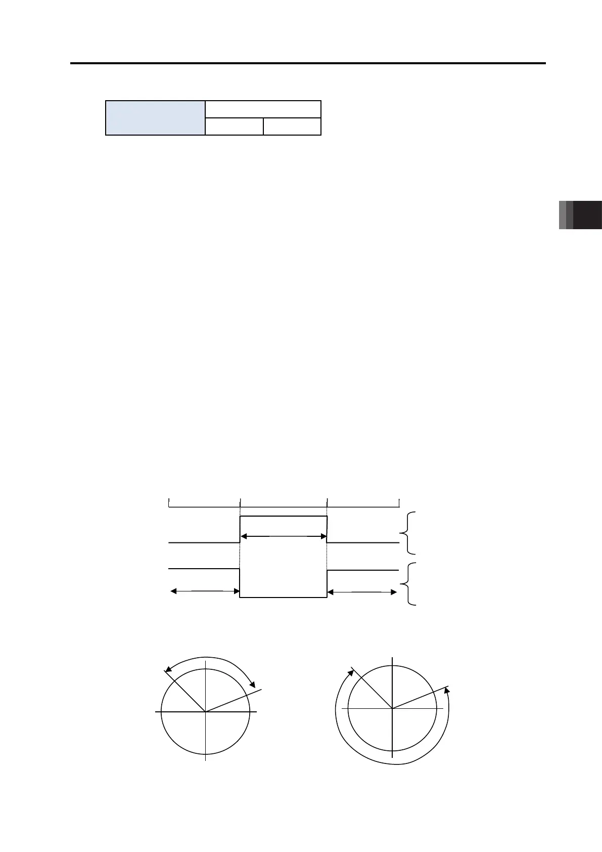
● Setting values and signal output range
The zone output range varies depending on the difference between the value set for the plus
side of the zone boundary and that for the minus side.
1) Value set for plus side > value set for minus side: The output signal is set to ON in the
range and OFF out of the range.
2) Value set for plus side < value set for minus side: The output signal is set to OFF in the
range and ON out of the range.
[For Straight Slide Actuators]
[Operation of rotary actuator of multi-rotation specification in index mode]
Zone boundary + : 70mm
Zone boundary - : 30mm
Zone boundary + : 30mm
Zone boundary - : 70mm
Zone boundary + : 70°
Zone boundary - : 315°
Zone boundary + : 315°
Zone boundary - : 70°

 Loading...


