6. Parameter
6.1 Parameter
6-7
ME0342-4B
6.1.2 Parameter Details
Caution
● After changing (writing) parameters, perform a software reset or power reboot so that the
set values can be reflected.
● The unit (deg) is applicable to the rotary actuator or lever-type gripper. Note that it will
be displayed as millimeter [mm] on the teaching tool.
[1] Zone Boundary 1 + Side, Zone Boundary 1 - Side (Parameter No. 1, No. 2)
Zone Boundary 2 + Side, Zone Boundary 2 - Side (Parameter No. 23, No. 24)
No. Name Unit Input range
Default initial value
setting
1 Zone boundary 1 + side
mm
(deg)
-9,999.99 to 9,999.99
Actual stroke on +
side
2 Zone boundary 1 - side
mm
(deg)
-9,999.99 to 9,999.99
Actual stroke on -
side
23 Zone boundary 2 + side
mm
(deg)
-9,999.99 to 9,999.99
Actual stroke on +
side
24 Zone boundary 2 - side
mm
(deg)
-9,999.99 to 9,999.99
Actual stroke on -
side
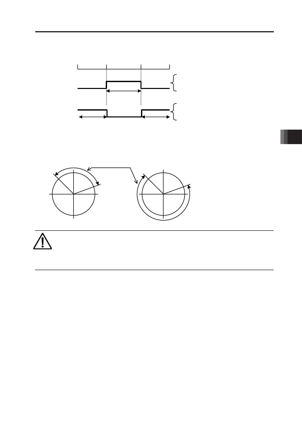
These parameters are used set the zone in which zone signal (ZONE1 or ZONE2) turns ON in a
mode other than PIO patterns 1 to 3.
The minimum setting unit is 0.01mm (deg).
If a specific value is set to both zone boundary + and zone boundary -, the zone signal is not
output.
A setting sample is shown below.
6.1 Parameter
ME0342-4B 6-8
[For linear axis]
[For rotary actuator in index mode]
Caution
● Unless the zone signal detection range is set at a value above minimum resolution, a
signal will not be output.
● The minimum resolution can be calculated with the equation below.
Minimum resolution [mm/pulse] = Actuator lead [mm/r] / Encoder resolution [pulse/r]
0° 0°
Set value
Zone boundary + side: 70mm
Zone boundary
- side: 30mm
Set value
Zone boundary + side: 30mm
Zone boundary
- side: 70mm

 Loading...


