6. Parameter
6.1 Parameter
6-9
ME0342-4B
[2] Soft Limit + Side, Soft Limit - Side (Parameter No. 3, No. 4)
No. Name Unit Input range
Default initial value setting
3 Soft limit + side
mm
(deg)
-9,999.99 to 9,999.99 Actual stroke on + side
4 Soft limit - side
mm
(deg)
-9,999.99 to 9,999.99 Actual stroke on - side
0.3 mm (deg) is added to the outside of the effective actuator stroke for the default setting.
Change as required to prevent collision when there are obstacles, or when used slightly above
effective stroke within the movable range.
The minimum setting unit is 0.01mm.
Caution
● At this time, take extra care not to set incorrect values as this will lead to a collision with
the mechanical end.
● If changing, set a value extended by 0.3mm to the outside of the effective stroke.
Example) To set the effective stroke between 0.0mm and 80.0mm
Parameter No.3 (+ side) 80.3
Parameter No.4 (- side) -0.3
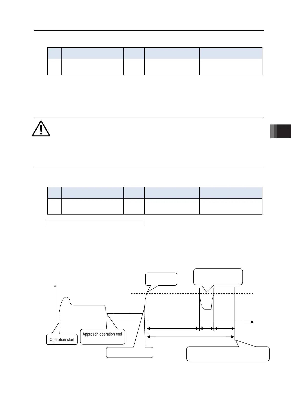
The movable range of jog or inching after home return will be 0.2mm inside the set value.
Alarm 0D9 "Software limit over error" occurs when the set value exceeds the value set in
parameter No. 88 "Soft limit margin" (default setting = 0). If parameter No. 88 is not set, the
value set for this parameter will become a detection value of the alarm 09D "Software limit over
error."
Approx. 0.3mm
0.2mm
Effective stroke
Software limit to set for the parameter
Approx. 0.3mm
0.2mm
80.0
Jog/inching movable range after home return
6.1 Parameter
ME0342-4B 6-10
[3] Homing Direction (Parameter No.5)
No. Name Unit Input range
Default initial value setting
5 Homing direction -
0: Reverse,
1: Forward
In accordance with actuator
Unless there is a request of Home Reversed Type (option), the home-return direction is on the
motor side for the line axis, counterclockwise side for the rotary axis and outer (open) side for the
gripper. Refer to [Actuator Coordinate System].
If it becomes necessary to reverse the home direction after the actuator is installed on the
machine, change the setting.
Caution
● Homing direction cannot be changed with some models.
● If it becomes necessary to reverse the homing direction after assembly to equipment,
check the model of the applicable actuator to ensure that the homing direction is
changeable.
● For models with which change is not possible, the actuator must be replaced.
Contact IAI if anything is unclear.
[4] Pushing Stop Recognition Time (Parameter No. 6)
No. Name Unit Input range
Default initial value setting
6
Pushing stop recognition
time
ms 0 to 9,999
In accordance with actuator
Judging completion of pressing operation
A parameter to set completion judgment time of push-motion operation (PIO pattern 0 to 3).
The torque (current limit value) set in percent [%] in "Pushing" in the position table is monitored,
and the pushing complete signal PEND turns ON when the load current reaches the following
conditions during push-motion operation. PEND signal turns ON when the conditions are
satisfied even if the workpiece is not stopped.
(Accumulated time in which current has reached push value [%]) - (accumulated time in which current is less than push value [%])
≥255ms (Parameter No.6)
Note 1 : The default is set to 70ms for some models of the gripper type.
Time
Contacting workpiece
Decrease in current
due to workpiece travel
200ms + 75ms - 20ms ≥ 255ms
(Note 1)
Push complete (PEND output)

 Loading...


