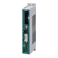
1. Controller Overview
1.3 Name for Each Parts and Their Functions
1-7
ME0342-4B
7) Axis Number Setting Switch
It is the switch to set the axis numbers when having an operation of multiple axes by the serial
communication, or when having the gateway operation.
Using the SIO converter allows multiple axes to be controlled on a teaching tool without
connection/disconnection of the connection cable connector. The SIO converter can specify up
to 16 axes with hexadecimal numbers 0 to F.
The setting of the switch is read at power-on of the controller. Changing the setting after the
power-on is invalid.
Caution
● Note duplicate axis number setting, which causes a communication error (alarm 30C:
no connection axis error) to occur and disables normal communication.
8) Operation Mode Setting Switch (MANU/AUTO)
The switch for interlock.
Setting to switch Operation status
AUTO
Allows auto operation by PIO signals. The
teaching tool can only operate the monitor.
MANU Allows the teaching tool to operate the controller.
9) SIO Connector (SIO)
The SIO connector is used to connect the controller with a teaching tool or a gateway unit
through a proper communication cable.
For details, refer to [3.3.5 SIO Connector Connection].
10) Motor • Encoder Connector
It is the connector to connect the actuator motor encoder cable.
For details, refer to [3.3.2 Connection to Actuator].
Point the arrow at a
desired
1.3 Name for Each Parts and Their Functions
ME0342-4B 1-8
11) Brake Release Switch (BK RLS/NOM)
For the actuator equipped with a brake, the switch is used to release the brake forcibly.
BK RLS ····· Brake forcible release
NOM ········· Normal operation (brake is activated)
Warning
● Always set the switch to “NOM” in normal operation.
(Make sure the opportunity to put the switch to RLS side is the minimum and is limited
to when startup and adjustment. Make certain to set the switch to NOM side in normal
use.)
The brake would not work even with the servo OFF condition if the switch is on the RLS
side. In the vertical oriented mount, the work may drop and cause an injury or the work
to be damaged.
12) Power Supply Connector
It is the connector for the power supply (for controller control power, actuator driving and brake
control power) and for the input of emergency status signal. For details, refer to [3.3.1 Wiring
Layout of Power Supply Connector].
13) Fan Unit
It is a forced cooling unit dedicated for PCON-CFB Type.
14) Fan Unit Desorption Lever
When fixing to a control box and replacing the fan unit, pull the lever up and the fan unit can be
taken out. When fixing, put the unit back on, and when replacing, attach a new unit, and push
the lever down to affix the unit.
Refer to [7.4.2 How to Replace Fan Unit] for how to take it off.

 Loading...