1. Controller Overview
1.4 Starting Procedures
1-9
ME0342-4B
1.4 Starting Procedures
Step1
Confirm all the necessary things are prepared (Contact us or our sales agency in case of any missing)
Refer to [2.1 Product Check] in this manual for more detail.
☆☆ Controller (PCON-CB) ☆☆ Actuator and Connection Cable
(The cable differs depending on the actuator type.)
* Check also enclosed parts
Refer to [2.1.1 Parts]
☆☆ Teaching pendant or PC software ☆☆ DVD Instruction Manual
IA-OS/RCM-101 (includes the following instruction manuals)
TB-02/TB-03
Refer to [Feature of Instruction Manual related to PCON-CB (page previous
to the table of contents)] for details
1) PCON-CB Instruction Manual (this manual)
2) RC PC Software Instruction Manual (ME0155)
☆☆ For Field Network Type: 3) Touch Panel Teaching Pendant Instruction Manual
For Field Network Setting
(
ME0324/ME0355/ME0376)
File (e.g. EDS File) 4) Each Field Network Instruction Manual (ME0254, etc.)
5) Each Instruction Manual of the Actuator
Download it in IAI homepage
(www.iai-robot.co.jp/)
Check the operation modes and control methods available on the controller you have purchased.
It can be defined on the controller model code shown on the label in the front face of the controller.
PCON-CB-20PWAI-NP-0-0
L=30
ST=8
RCP2-GRSS
1) CB/CGB (Standard type)
2) CFB/CGFB (High-thrust actuator connection type)
3) CBP/CGBP (Dedicated for pulse pressing)
1) NP/PN (Dedicated for positioner operation)
2) PLN/PLP (Select from positioner operation and pulse train
control)
3) Others (Dedicated for field network control)
1.4 Starting Procedures
ME0342-4B 1-10
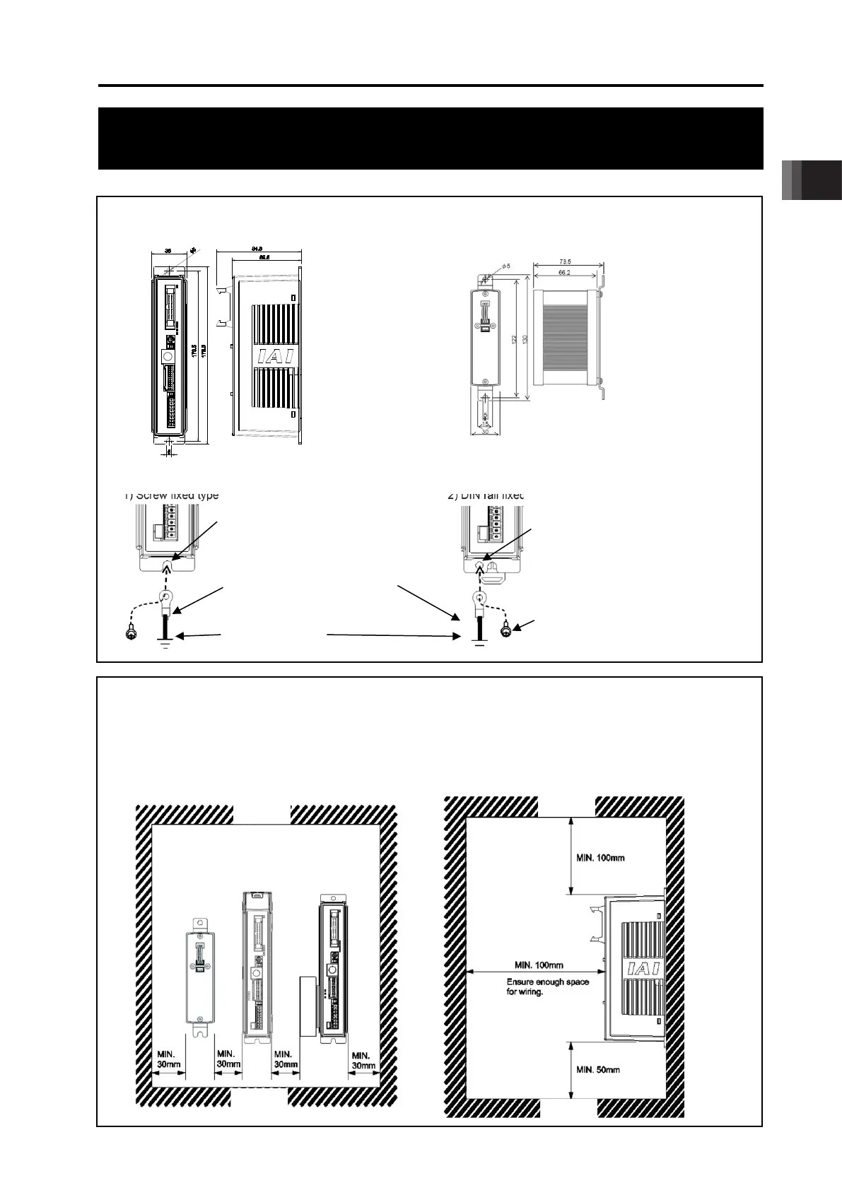
Step2 Installation
External Dimensions * Check in [2.4 External View] as they differ for each type.
Controller Absolute Battery Unit
(option for Simple Absolute Type)
Noise Elimination Grounding (Frame Ground)
1) Screw fixed type 2) DIN rail fixed type
Heat Radiation and Installation
Keep the ambient temperature of the controller at 40°C or less.
To fix the units in the control box, use the attachment holes on top and bottom of the unit for the screw
fixed type, and use the DIN rails for the DIN rail fixed type. Install in the orientation shown in the figure
below for heat radiation.
CFB (screw affixed type), detach the fan unit once and use the attachment holes on the top. Refer to
[2.8.2 (2) Installation of CFB Type]
Connect the ground line
together to the main unit
using the fixing screw.
Copper Wire:
Connect to a ground
cable with
2
) or more.
Connect the ground cable using
the
screw hole for FG connection
M3 x 5 nickeled pan head machine screw
(enclosure dedicated for
Grounding resistance at 100Ω or less)

 Loading...


