Intel
®
Server Chassis P4304XXMFEN2/P4304XXMUXX Product Family System Integration and Service Guide
136
7.4 Replacing the Server Board
7.4.1 Server Board Removal
1. Power off system and remove power cords from each power supply module installed.
2. Disconnect all externally attached cables.
3. Remove the chassis side cover by following instructions in section 1.2.1
4. Remove air duct by following instructions in section 1.2.2.1.
5. Disconnect all cables attached to PCIe* add-in cards (if installed).
6. Remove all options installed onto the server board including (if installed): Intel® RAID 5 option key, Intel®
RMM 4 Lite key, TPM Module, and any installed PCIe* add-in cards.
7. Remove processors by following instructions in section 2.1.
8. Remove all DIMMs by following instructions in section 2.2.3.
9. Disconnect and clear from the server board area all cables attached to connectors on the server board
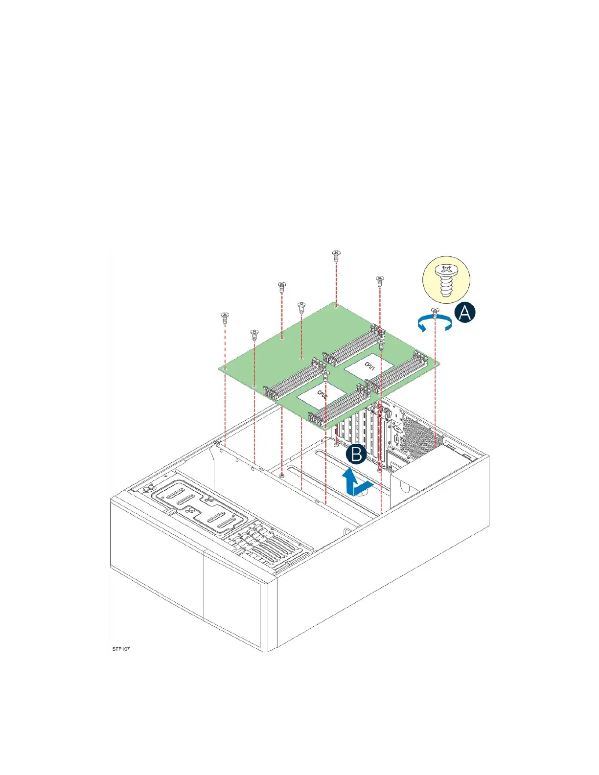
Figure 154. Server Board Removal
10. Remove nine screws used to secure the server board to the chassis (see Letter A).
11. Carefully lift the server board from the chassis and place it into an anti-static bag (see letter B).