Intel
®
Server Chassis P4304XXMFEN2/P4304XXMUXX Product Family System Integration and Service Guide
29
5. If present, remove the protective film covering the TIM on the bottom side of the heat sink.
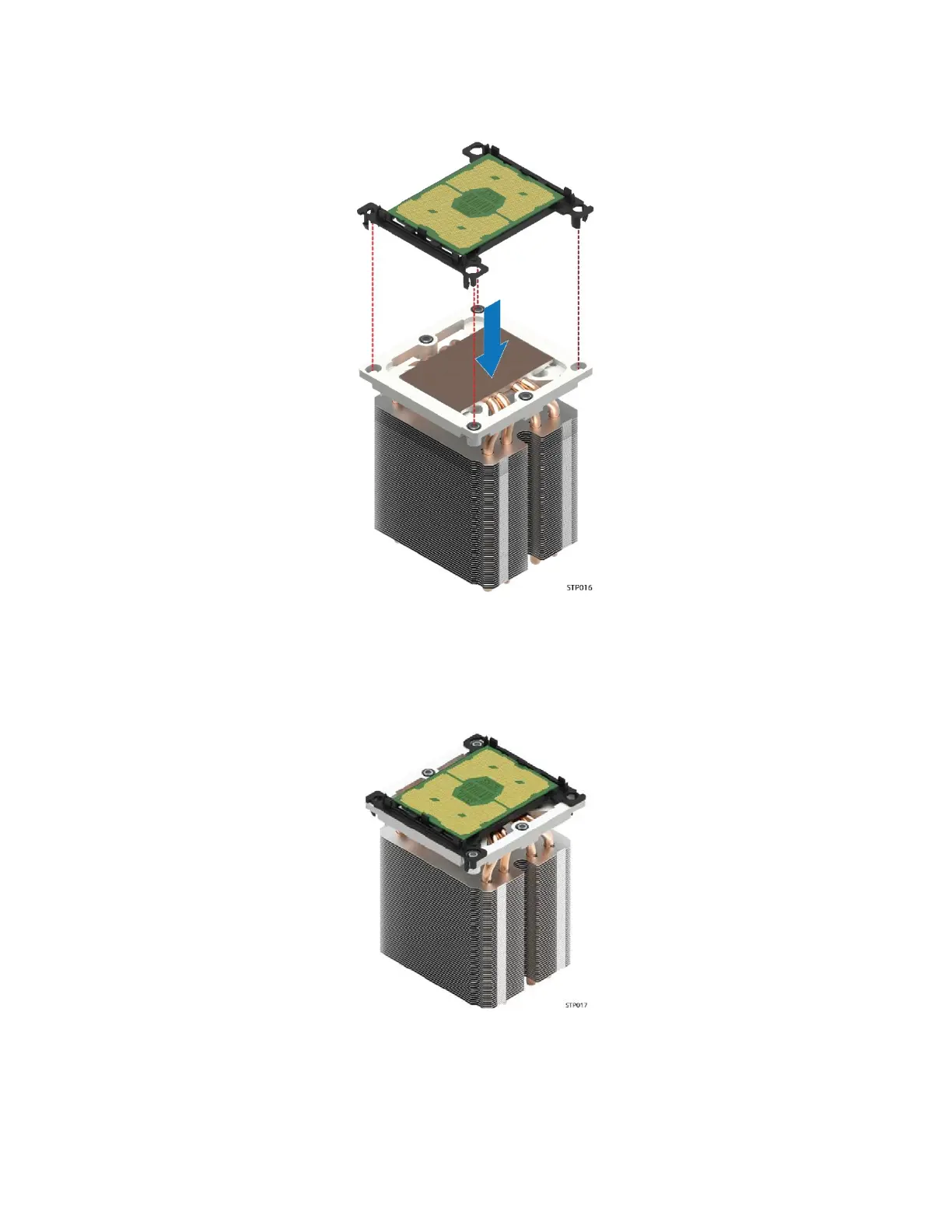
6. Orient the processor sub-assembly over the processor heat sink so that all corner features are in
alignment.
Figure 35. Processor and CarrierClip Sub-Assembly to Heat Sink
7. Push the processor sub-assembly down on to the processor heat sink until it snaps into place,
ensuring all four corners are secure.
Figure 36. Processor Heat Sink Module (PHM)